Qashqai J11. Front axle — part 4

FRONT WHEEL HUB AND KNUCKLE
FAX-49
< REMOVAL AND INSTALLATION >
[4WD]
C
E
F
G
H
I
J
K
L
M
A
B
FAX
N
O
P
REMOVAL AND INSTALLATION
FRONT WHEEL HUB AND KNUCKLE
Exploded View
INFOID:0000000010297864
Removal and Installation
INFOID:0000000010297865
REMOVAL
Wheel hub
1.
emove tires from vehicle.
2.
Remove wheel sensor (1) from steering knuckle. Refer to
138, "FRONT WHEEL SENSOR : Exploded View"
CAUTION:
• Failure to separate the front wheel sensor from the steer-
ing knuckle may result in damage to the front wheel sen-
sor.
• Never pull on wheel sensor harness.
3.
Remove lock plate from strut assembly. Refer to
BR-19, "FRONT : Exploded View"
(LHD),
4.
Remove torque member mounting bolts. Hang torque member not to interfere with work. Refer to
"BRAKE CALIPER ASSEMBLY : Exploded View"
(LHD),
BR-80, "BRAKE CALIPER ASSEMBLY :
(RHD).
CAUTION:
Never depress brake pedal while brake caliper is removed.
5.
Remove disc rotor.
6.
Remove cotter pin, and then loosen hub lock nut.
1.
Steering knuckle
2.
Splash guard
3.
Wheel hub and bearing assembly
4.
Cotter pin
Refer to
E1DIA0224GB
ALDIA0526ZZ

FAX-50
< REMOVAL AND INSTALLATION >
[4WD]
FRONT WHEEL HUB AND KNUCKLE
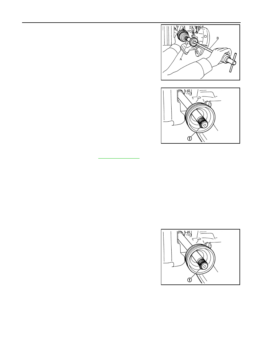
7.
Patch hub lock nut with a piece of wood. Hammer the wood to
disengage wheel hub and bearing assembly from drive shaft.
Remove the hub lock nut.
CAUTION:
• Never place drive shaft joint at an extreme angle. Also be
careful not to overextend slide joint.
• Never allow drive shaft to hang down without support for
housing (or joint sub-assembly), shaft and the other parts.
NOTE:
Use suitable puller, if wheel hub and bearing assembly and drive
shaft cannot be separated even after performing the above pro-
cedure.
8.
Remove the wheel hub lock nut.
9.
Remove the engine side cover.
10. Remove the lower nut and bolt from the steering knuckle. Refer to
.
11. Separate transverse link from steering knuckle.
12. Separate drive shaft from wheel hub and bearing, Reposition the drive shaft aside with wire.
13. Remove the wheel hub and bearing bolts using power tool.
14. Remove the splash guard and the wheel hub and bearing from the steering knuckle.
Steering knuckle
1.
Remove wheel hub and bearing assembly, and then remove splash guard.
2.
Remove cotter pin (1) of steering outer socket, and then loosen
the nut.
3.
Remove steering outer socket (2) from steering knuckle (3)
using the ball joint remover so as not damage ball joint boot (4).
CAUTION:
Temporarily tighten the nut to prevent damage to threads
and to prevent the ball joint remover from suddenly coming
off.
4.
Remove transverse link from steering knuckle.
5.
Remove steering knuckle from strut assembly.
6.
Remove steering knuckle from vehicle.
INSTALLATION
Note the following, and install in the reverse order of the removal.
CAUTION:
• Never reuse the wheel stud.
• Never reuse the cotter pin.
• Place a washer (A) as shown to install the wheel studs (1) by using
the tightening force of the nut (B).
CAUTION:
Check that there is no clearance between the wheel stud and
the wheel hub and bearing.
• Clean the mating surfaces of the wheel hub lock nut and the wheel hub and bearing.
CAUTION:
Never apply lubricating oil to these mating surfaces.
JPDIF0003ZZ
SGIA1183E
JPDIF0300ZZ

FRONT WHEEL HUB AND KNUCKLE
FAX-51
< REMOVAL AND INSTALLATION >
[4WD]
C
E
F
G
H
I
J
K
L
M
A
B
FAX
N
O
P
• Clean the mating surfaces of the joint sub-assembly and the wheel
hub and bearing. Apply Molykote M77 lubricant to the surface (A)
of the joint sub-assembly.
CAUTION:
Apply lubricant to cover the entire flat mating surface of the
joint sub-assembly.
NOTE:
Always check with the Parts Department for the latest parts informa-
tion.
• Hold the wheel hub and bearing using a suitable tool. Tighten the wheel hub lock nut.
CAUTION:
• Since the drive shaft is assembled by press-fitting, use a torque wrench to tighten the wheel hub
lock nut. Do not use a power tool.
• Too much torque causes axle noise. Too little torque causes wheel bearing looseness. Tighten the
wheel hub lock nut to the specification.
• When installing a the cotter pin (1) and the nut retainer (2),
securely bend the cotter pin to prevent rattles.
• Align the matching marks (A) on the disc brake rotor and on the
wheel hub and bearing.
• Complete the inspection. Refer to
.
Inspection
INFOID:0000000010297866
INSPECTION AFTER REMOVAL
Check components for deformation, cracks, and other damage. Replace if there are.
Ball Joint Inspection
Check boots of transverse link and steering outer socket ball joint for breakage, axial play, and torque. Refer to
.
INSPECTION AFTER INSTALLATION
• Check the wheel alignment. Refer to
FSU-7, "Wheel Alignment Inspection"
.
• Adjust neutral position of steering angle sensor after checking the wheel alignment. Refer to
Amount of lubricant
JPDIG0122ZZ
JPDIF0295ZZ
JPDIG0066ZZ

FAX-52
< REMOVAL AND INSTALLATION >
[4WD]
FRONT DRIVE SHAFT BOOT
FRONT DRIVE SHAFT BOOT
Exploded View
INFOID:0000000010435905
REMOVAL
LEFT SIDE
RIGHT SIDE (MR20DD)
RIGHT SIDE (R9M)
E1DIA0230GB
1.
Drive shaft
2.
Cotter pin
Refer to
for symbols in the figure.
E1DIA0232GB
1.
Cotter pin
2.
Drive shaft
3.
Plate
4.
Support bearing bracket
Refer to
for symbols in the figure.
AWDIA1158ZZ

FRONT DRIVE SHAFT BOOT
FAX-53
< REMOVAL AND INSTALLATION >
[4WD]
C
E
F
G
H
I
J
K
L
M
A
B
FAX
N
O
P
DISASSEMBLY
LEFT SIDE
RIGHT SIDE (MR20DD)
1.
Cotter pin
2.
Nut retainer
3.
Drive shaft
Refer to
JPDIF0047ZZ
1.
Circular clip
2.
Dust shield
3.
Housing
4.
Snap ring
5.
Spider assembly
6.
stopper ring
7.
Boot band
8.
Boot
9.
Shaft
10. Damper band
11.
Dynamic damper
12. Circular clip
13. Joint sub-assembly
: Wheel side
: Fill NISSAN Genuine grease or equivalent.
Refer to
for symbols not described on the above.
JPDIF0045ZZ
1.
Joint sub-assembly
2.
Circular clip
3.
Boot band
4.
Boot
5.
Shaft
6.
Damper band
7.
Dynamic damper
8.
Stopper ring
9.
Spider assembly
10. Snap ring
11.
Housing assembly
12. Dust shield

FAX-54
< REMOVAL AND INSTALLATION >
[4WD]
FRONT DRIVE SHAFT BOOT
RIGHT SIDE (R9M)
WHEEL SIDE
WHEEL SIDE : Removal and Installation
INFOID:0000000010435907
REMOVAL
1.
Remove tires from vehicle.
13. Support bearing
14. Snap ring
15. Dust shield
: Wheel side
: Fill NISSAN Genuine grease or equivalent.
Refer to
for symbols not described on the above.
AWDIA1159ZZ
1.
Joint sub-assembly
2.
Circular clip
3.
Boot band
4.
Boot
5.
Shaft
6.
Stopper ring
7.
Spider assembly
8.
Snap ring
9.
Housing assembly
10. Dust shield
11.
Support bearing
12. Plate
13. Support bearing bracket
: Wheel side
: Fill NISSAN Genuine grease or equivalent.
Refer to
for symbols not described on the above.

FRONT DRIVE SHAFT BOOT
FAX-55
< REMOVAL AND INSTALLATION >
[4WD]
C
E
F
G
H
I
J
K
L
M
A
B
FAX
N
O
P
2.
Remove the bolt (1) and separate the front wheel sensor from
the steering knuckle. Refer to
SOR : Removal and Installation"
.
CAUTION:
• Failure to separate the front wheel sensor from the steer-
ing knuckle may result in damage to the front wheel sen-
sor.
• Never pull on wheel sensor harness.
3.
Remove torque member mounting bolts. Hang torque member
not to interfere with work. Refer to
CAUTION:
Never depress brake pedal while brake caliper is removed.
4.
Put alignment marks (A) on disc brake rotor and wheel hub and
bearing. Remove disc brake rotor.
CAUTION:
Never drop the disc brake rotor.
5.
Remove cotter pin.
6.
Remove the nut retainer.
7.
Loosen the wheel hub lock nut from the drive shaft using power tool.
8.
Patch hub lock nut with a piece of wood. Hammer the wood to
disengage wheel hub and bearing assembly from drive shaft.
Remove the hub lock nut.
CAUTION:
• Never place the drive shaft joint at an extreme angle. Also
be careful not to overextend slide joint.
• Never allow the drive shaft to hang down without support-
for housing (or joint sub-assembly), shaft and the other
parts.
NOTE:
Use suitable puller if wheel hub and drive shaft cannot be sepa-
rated even after performing the above procedure.
9.
Remove the lower nut and bolt from the steering knuckle (shown in explode). Separate the transverse link
from the steering knuckle. Refer to
.
10. Separate drive shaft from wheel hub and bearing, Reposition the drive shaft aside with wire. Refer to
11. Remove boot bands.
12. Remove boot from joint sub-assembly.
ALDIA0526ZZ
JPDIG0066ZZ
JPDIG0070ZZ
FAX-56
< REMOVAL AND INSTALLATION >
[4WD]
FRONT DRIVE SHAFT BOOT
13. Screw a drive shaft puller (A) into joint sub-assembly screw part
to a length of 30 mm (1.18 in) or more. Support drive shaft with
one hand and pull out joint sub-assembly with a sliding hammer
(B) from shaft.
CAUTION:
• Align a sliding hammer and drive shaft and remove them
by pulling firmly and uniformly.
• If joint sub-assembly cannot be pulled out, try after
removing drive shaft from vehicle.
14. Remove circular clip (1) from shaft (exept for R9M) our housing
assembly (R9M).
15. Remove outer boot from shaft.
16. Inspect the components. Refer to
.
INSTALLATION
1.
Clean the old grease on joint sub-assembly with paper shop cloth.
2.
Fill serration slot joint sub-assembly with NISSAN genuine grease or equivalent.
CAUTION:
After applying grease, use a paper shop cloth to wipe off old grease that has oozed out.
NOTE:
Always check with the Parts Department for the latest parts information.
3.
Install boot and boot bands to shaft.
CAUTION:
• Wrap serration on shaft with tape to protect the boot from damage.
• Never reuse boot and boot band.
4.
Remove the tape wrapped around the serration on shaft.
5.
Position the circular clip (1) on groove at the shaft edge.
CAUTION:
Never reuse circular clip.
NOTE:
A drive joint inserter is recommended when installing the circular
clip.
6.
Align of the shaft and joint sub-assembly. Assemble the shaft with joint sub-assembly while holding the cir-
cular clip.
JPDIF0022ZZ
JPDIF0007ZZ
JPDIF0007ZZ

FRONT DRIVE SHAFT BOOT
FAX-57
< REMOVAL AND INSTALLATION >
[4WD]
C
E
F
G
H
I
J
K
L
M
A
B
FAX
N
O
P
7.
Install joint sub-assembly (1) to housing assembly using suitable
tool.
CAUTION:
Confirm that joint sub-assembly is correctly engaged while
rotating drive housing assembly.
8.
Apply the specified amount of grease into the large diameter side opening of the boot.
9.
Install the boot securely into grooves (indicated by “*” marks)
shown in the figure.
CAUTION:
If grease adheres to the boot mounting surface (indicated
by “*” mark) on the shaft or the joint sub-assembly, boot
may come off. Remove all grease from the boot mounting
surface.
10. Make sure boot installation length (L) is the specified length.
Insert a suitable tool into the large end of boot. Bleed air from
boot to prevent boot deformation.
CAUTION:
• Boot may break if boot installation length is not within standard value.
• Be careful that suitable tool does not contact inside surface of boot.
11. Install new large and small boot bands securely using Tool.
CAUTION:
Never reuse boot band.
12. Secure boot band so that dimension (M) meets the specification
as shown.
13. Attempt to rotate the boot to check whether or not the boot bands are securing the boot. If the boot is not
secure, remove the boot bands, reposition the boot, and install new boot bands.
JPDIF0011ZZ
Grease amount
: Refer to
.
Boot installation
length (L)
: Refer to
.
Tool number
: KV40107300 (
—
)
JPDIF0222ZZ
RAC1133D
Dimension (M)
DSF0047D

FAX-58
< REMOVAL AND INSTALLATION >
[4WD]
FRONT DRIVE SHAFT BOOT
14. Clean the mating surfaces of the joint sub-assembly and the
wheel hub and bearing. Apply Molykote M77 lubricant to the sur-
face (A) of the joint sub-assembly.
CAUTION:
Apply lubricant to cover the entire flat mating surface of the
joint sub-assembly.
NOTE:
Always check with the Parts Department for the latest parts
information.
15. Clean the mating surface of the drive shaft (A) and the wheel hub and bearing.
16. Insert drive shaft to wheel hub and bearing.
17. Temporarily install the wheel hub lock nut.
CAUTION:
Never reuse the wheel hub lock nut.
18. Install the transverse link to the steering knuckle. Tighten the steering knuckle nut and bolt to the specifi-
cation. Refer to
.
19. Align the marks on the disc brake rotor and on the wheel hub and bearing. Install the disc brake rotor.
20. Install caliper to steering knuckle. Refer to
BR-37, "BRAKE CALIPER ASSEMBLY : Removal and Installa-
21. Install the front wheel sensor to the steering knuckle. Refer to
BRC-138, "FRONT WHEEL SENSOR :
.
CAUTION:
• Before installling, make sure there is no foreign material such as iron fragments adhered to the
pick-up part of the front wheel sensor.
• When installing, make sure there is no foreign material such as iron fragments on and in the hole
in the steering knuckle for the front wheel sensor. Make sure no foreign material has been
caught in the sensor rotor. Remove any foreign material and then install the front wheel sensor.
22. Hold the wheel hub and bearing. tighten the wheel hub lock nut. Refer to
CAUTION:
• Since the drive shaft is assembled by press-fitting, use a torque wrench to tighten the wheel hub
lock nut. Do not use a power tool.
• Too much torque causes axle noise. too little torque causes wheel bearing loosness. Tighten the
wheel hub lock nut to the specification.
23. Install the nut retainer.
24. Install a new cotter pin. Refer to
CAUTION:
• Never reuse cotter pin.
• Bend cotter pin securely to prevent any looseness.
25. Install the front wheel and tire. Refer to
WT-60, "Wheel Balance Adjustment (Aluminum Wheel)"
TRANSAXLE SIDE
TRANSAXLE SIDE : Removal and Installation
INFOID:0000000010435908
NOTE:
Remove boot after removing drive shaft.
• For drive shaft removal and installation, refer to
FAX-60, "Removal and Installation (LH)"
• For drive shaft disassembly and assembly, refer to
FAX-68, "Disassembly and Assembly"
Inspection
INFOID:0000000010435909
INSPECTION AFTER INSTALLATION
Amount of lubricant
JPDIG0122ZZ

FRONT DRIVE SHAFT BOOT
FAX-59
< REMOVAL AND INSTALLATION >
[4WD]
C
E
F
G
H
I
J
K
L
M
A
B
FAX
N
O
P
Check the following items, and replace the part if necessary.
• Move joint up/down, left/right, and in the axial directions. Check for
motion that is not smooth and for significant looseness.
• Check boot for cracks, damage, and leakage of grease.
• Check the wheel sensor harness to be sure the connectors are
fully seated.
• Check the wheel alignment. Refer to
.
SDIA1190J

FAX-60
< REMOVAL AND INSTALLATION >
[4WD]
FRONT DRIVE SHAFT
FRONT DRIVE SHAFT
Exploded View (LH)
INFOID:0000000010435950
Removal and Installation (LH)
INFOID:0000000010435951
REMOVAL
1.
Remove tires from vehicle.
2.
Remove the bolt (1) and separate the front wheel sensor from
the steering knuckle. Refer to
SOR : Removal and Installation"
.
CAUTION:
• Failure to separate the front wheel sensor from the steer-
ing knuckle may result in damage to the front wheel sen-
sor.
• Never pull on wheel sensor harness.
3.
Remove torque member mounting bolts. Hang torque member
not to interfere with work. Refer to
CAUTION:
Never depress brake pedal while brake caliper is removed.
4.
Put alignment marks (A) on disc brake rotor and wheel hub and
bearing. Remove disc brake rotor.
CAUTION:
Never drop the disc brake rotor.
5.
Remove cotter pin.
6.
Remove the nut retainer.
7.
Loosen the wheel hub lock nut from the drive shaft using power tool.
1.
Drive shaft
2.
Cotter pin
Refer to
for symbols in the figure.
E1DIA0230GB
ALDIA0526ZZ
JPDIG0066ZZ

FRONT DRIVE SHAFT
FAX-61
< REMOVAL AND INSTALLATION >
[4WD]
C
E
F
G
H
I
J
K
L
M
A
B
FAX
N
O
P
8.
Patch hub lock nut with a piece of wood. Hammer the wood to
disengage wheel hub and bearing assembly from drive shaft.
Remove the hub lock nut.
CAUTION:
• Never place the drive shaft joint at an extreme angle. Be
careful not to over extend the slide joint.
• Never allow drive shaft to hangdown without support for
housing (or joint sub-assembly), shaft and the other parts.
NOTE:
Use a suitable puller iff drive shaft cannot be separated from the
wheel hub and bearing.
9.
Remove the lower nut and bolt from the steering knuckle (shown in explode). Separate the transverse link
from the steering knuckle. Refer to
10. Separate drive shaft from wheel hub and bearing, Reposition the drive shaft aside with wire.
11. Remove drive shaft from transaxle assembly.
• Use the Tool (A) and a suitable tool (B) while inserting tip of
Tool (A) between housing and transaxle assembly.
CAUTION:
• Never place drive shaft joint at an extreme angle when
removing drive shaft. Also be careful not to overextend
slide joint.
• Confirm that the circular clip is attached to the drive
shaft.
INSTALLATION
Installation is in the reverse order of removal.
• Install a new differential side oil seal.
CAUTION:
Never reuse the differential side oil seal.
• Place Tool (A) onto transaxle assembly to prevent damage to the
differential side oil seal while inserting drive shaft. Slide drive shaft
sliding joint and tap with a suitable tool to install securely.
CAUTION:
Check that circular clip is completely engaged.
• Clean the matching surface of wheel hub lock nut and wheel hub and bearing.
CAUTION:
Never apply lubricating oil to these matching surface.
• Clean the mating surfaces of the joint sub-assembly and the wheel
hub and bearing. Apply Molykote M77 lubricant to the surface (A)
of the joint sub-assembly.
CAUTION:
Apply lubricant to cover the entire flat mating surface of the
joint sub-assembly.
NOTE:
JPDIG0070ZZ
Tool (A)
: KV40107500 ( –– )
JPDIF0004ZZ
Tool (A)
: KV38107900 ( –– )
JPDIF0023ZZ
Amount of lubricant
:
JPDIG0122ZZ

FAX-62
< REMOVAL AND INSTALLATION >
[4WD]
FRONT DRIVE SHAFT
Always check with the Parts Department for the latest parts information.
• Hold the wheel hub and bearing using a suitable tool. Tighten the wheel hub lock nut.
CAUTION:
• Since the drive shaft is assembled by press-fitting, use a torque wrench to tighten the wheel hub
lock nut. Do not use a power tool.
• Too much torque causes axle noise. Too little torque causes wheel bearing looseness. Tighten the
wheel hub lock nut to the specification.
• Align the matching marks that have been made during removal when reusing the disc brake rotor.
• When installing a cotter pin (1) and nut retainer (2), securely bend
the cotter pin to prevent rattles.
CAUTION:
Never reuse cotter pin.
• Perform the final tightening of each of parts under unladen condi-
tions, which were removed when removing wheel hub and bearing
and steering knuckle.
Exploded View (RH)
INFOID:0000000010435952
MR20DD :
R9M :
JPDIF0295ZZ
1.
Cotter pin
2.
Drive shaft
3.
Plate
4.
Support bearing bracket
Refer to
for symbols in the figure
E1DIA0232GB

FRONT DRIVE SHAFT
FAX-63
< REMOVAL AND INSTALLATION >
[4WD]
C
E
F
G
H
I
J
K
L
M
A
B
FAX
N
O
P
Removal and Installation (RH)
INFOID:0000000010435953
REMOVAL
1.
Remove tires from vehicle.
2.
Remove the bolt (1) and separate the front wheel sensor from
the steering knuckle. Refer to
SOR : Removal and Installation"
.
CAUTION:
• Failure to separate the front wheel sensor from the steer-
ing knuckle may result in damage to the front wheel sen-
sor.
• Never pull on wheel sensor harness.
3.
Remove torque member mounting bolts. Hang torque member not to interfere with work. Refer to
"BRAKE CALIPER ASSEMBLY : Exploded View"
(LHD),
BR-80, "BRAKE CALIPER ASSEMBLY :
(RHD).
CAUTION:
Never depress brake pedal while brake caliper is removed.
4.
Put alignment marks (A) on disc brake rotor and wheel hub and
bearing. Remove disc brake rotor.
CAUTION:
Never drop the disc brake rotor.
5.
Remove cotter pin.
6.
Remove the nut retainer.
7.
Loosen the wheel hub lock nut from the drive shaft using power tool.
1.
Cotter pin
2.
Nut retainer
3.
Drive shaft
Refer to
AWDIA1158ZZ
ALDIA0526ZZ
JPDIG0066ZZ
FAX-64
< REMOVAL AND INSTALLATION >
[4WD]
FRONT DRIVE SHAFT
8.
Patch hub lock nut with a piece of wood. Hammer the wood to
disengage wheel hub and bearing assembly from drive shaft.
Remove the hub lock nut.
CAUTION:
• Never place the drive shaft joint at an extreme angle. Be
careful not to over extend the slide joint.
• Never allow drive shaft to hangdown without support for
housing (or joint sub-assembly), shaft and the other parts.
NOTE:
Use a suitable puller if drive shaft cannot be separated from the
wheel hub and bearing.
9.
Remove the lower nut and bolt from the steering knuckle (shown in explode). Separate the transverse link
from the steering knuckle. Refer to
10. Separate drive shaft from wheel hub and bearing and reposition drive shaft aside with wire.
11. Remove retainer mounting bolts and retainer.
12. If necessary, remove the support bearing bracket mounting bolts and the support bearing bracket.
13. Remove drive shaft from transaxle assembly.
• Use the Tool (A) and a suitable tool (B) while inserting tip of Tool (A) between housing and transaxle
assembly.
CAUTION:
• Never place drive shaft joint at an extreme angle when removing drive shaft. Also be careful
not to overextend slide joint.
INSTALLATION
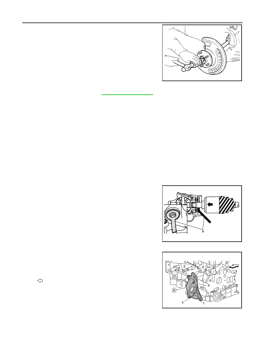
1.
Install a new differential side oil seal.
CAUTION:
Never reuse the differential side oil seal.
2.
Place Tool (A) onto transaxle assembly to prevent damage to
the differential side oil seal while inserting drive shaft. Slide drive
shaft sliding joint and tap with a suitable tool to install securely.
CAUTION:
Check that circular clip is completely engaged.
Support bearing bracket
1.
Install front drive shaft and bearing retainer with notch (A) facing
upward.
2.
Tighten bolts in the numerical order as shown.
• Refer to the following for the installation positions of bolts.
JPDIG0070ZZ
Tool
: KV40107500 ( –– )
Tool : KV38107900 ( –– )
JPDIF0023ZZ
: Front
M12 bolts
: No. 1
97.1 N·m (9.9 kg-m,
72 ft-lb)
M10 bolts
: No. 2, 3
48.0 N·m (4.9 kg-m,
35 ft-lb)
M8 bolts
: No. 4, 5
25.0 N·m (2.6 kg-m,
18 ft-lb)
ALDIA0527ZZ
Нет комментариевНе стесняйтесь поделиться с нами вашим ценным мнением.
Текст