Nissan Primera P12. Manual — part 139

TROUBLE DIAGNOSIS
BRC-61
[ESP/TCS/ABS]
C
D
E
G
H
I
J
K
L
M
A
B
BRC
Data monitor item
Contents
Data monitor
(Reference) Check items
for malfunction
Condition
Reference value in
normal operation
FR RH SENSOR
FR LH SENSOR
RR RH SENSOR
RR LH SENSOR
Wheel speed (Note 1)
Vehicle stopped
0 [km/h (MPH)]
Wheel sensor circuit
During driving
Almost in accor-
dance with the
speedometer dis-
play (within
±
10%)
ACCEL POS SIG
Open/close condition
of throttle valve (linked
with accelerator pedal)
Accelerator pedal not
depressed (ignition switch is
ON)
0%
Control unit communica-
tion circuit between the
ESP/TCS/ABS control
unit and ECM
Accelerator pedal depressed
(ignition switch is ON)
0 – 100%
ENGINE RPM
With the engine run-
ning
With the engine stopped
0rpm
Engine speed signal cir-
cuit
Engine running
Almost in accor-
dance with
tachometer display
STR ANGLE SIG
Steering angle
detected by steering
angle sensor
Straight-ahead condition
Approx. 0 deg
Steering angle sensor
and circuit
Steering
– 720 to 720deg
YAW RATE SEN
Yaw rate detected by
yaw rate sensor
Vehicle stopped
Approx. 0 d/s
Yaw rate sensor and cir-
cuit
During driving
– 70 to 70d/s
SIDE G-SENSOR
Transverse accelera-
tion detected by side G
sensor
Vehicle stopped
Approx. 0 m/s
2
Side G sensor and circuit
During driving
– 24.3 to 24.1m/s
2
PRESS SENSOR
Brake fluid pressure
detected by pressure
sensor
With the ignition switch
turned ON and brake pedal
released.
Approx. 0 bar
Pressure sensor and cir-
cuit
With the ignition switch
turned ON and brake pedal
depressed.
– 40 to 300bar
BATTERY VOLT
Battery voltage sup-
plied to the ESP/TCS/
ABS control unit
Ignition switch ON
10 – 16V
ESP/TCS/ABS control
unit power supply circuit
and ground circuit
MOTOR RELAY
Motor relay
ON/OFF condition
ABS not activated.
OFF
Motor relay and circuit
ABS activated.
ON
ACTUATOR RLY
Actuator relay
ON/OFF condition
Ignition ON and Vehicle
stopped.
OFF
Actuator relay and circuit
Engine running and Vehicle
stopped.
ON
STOP LAMP SW
Operating status of
brake pedal
Depress brake pedal.
ON
Stop lamp switch circuit
Release the brake pedal.
OFF
PARK BRAKE SW
Parking brake status
Parking brake activated
ON
Parking brake switch cir-
cuit
Parking brake not activated
OFF
OFF SW
ESP OFF SW
ON/OFF condition
ESP OFF switch ON
(When ESP OFF indicator
lamp is ON.)
ON
ESP OFF switch circuit
ESP OFF switch OFF
(When ESP OFF indicator
lamp is OFF.)
OFF
ABS WARN LAMP
ABS warning lamp sta-
tus (Note 2)
When ABS warning lamp is
ON.
ON
ABS warning lamp circuit
When ABS warning lamp is
OFF.
OFF

BRC-62
[ESP/TCS/ABS]
TROUBLE DIAGNOSIS
(Note 1): Check the pressure of the tire in normal condition.
(Note 2): ON/OFF timing of the ABS warning lamp
ON: For approximately 0.5 seconds after the ignition switch is turned ON, or when a malfunction is detected.
OFF: Approximately 0.5 seconds after the ignition switch is turned ON (when the system is in normal operation).
(Note 3): ON/OFF timing of the ESP OFF indicator lamp
ON: For approximately 0.5 seconds after the ignition switch is turned ON, or when a malfunction is detected ESP OFF switch is ON.
OFF: Approximately 0.5 seconds after the ignition switch is turned ON (when the system is in normal operation) or when ESP OFF
switch is OFF.
(Note 4): SLIP indicator lamp ON/OFF timing
ON: For approximately 0.5 seconds after the ignition switch is turned ON, or when a malfunction is detected.
OFF LAMP
ESP OFF indicator
lamp status (Note 3)
When ESP OFF indicator
lamp is ON.
ON
ESP OFF indicator lamp
circuit
When ESP OFF indicator
lamp is OFF.
OFF
SLIP LAMP
SLIP indicator lamp
status (Note 4)
When SLIP indicator lamp is
ON
ON
SLIP indicator lamp cir-
cuit
When SLIP indicator lamp is
OFF
OFF
FR LH IN SOL
FR LH OUT SOL
FR RH IN SOL
FR RH OUT SOL
RR LH IN SOL
RR LH OUT SOL
RR RH IN SOL
RR RH OUT SOL
Solenoid valve opera-
tion
Actuator (solenoid valve) is
active (“Active Test ”with CON-
SULT-II) or actuator relay is
inactive (in fail-safe mode).
ON
Solenoid valve and cir-
cuit
When the actuator (solenoid
valve) is not active and actua-
tor relay is active (ignition
switch ON).
OFF
USV [FR-RL]
USV [FL-RR]
HSV [FR-RL]
HSV [FL-RR]
ESP switch-over sole-
noid valve status
When the actuator (switch-
over solenoid valve) is active
(
″
Active test
″
with CONSULT-
II) or the actuator relay is inac-
tive (when fail-safe mode).
ON
Switch-over solenoid
valve and circuit
When the actuator (switch-
over solenoid valve) is inactive
or the actuator relay is active
(ignition switch ON).
OFF
V/R OUTPUT
Actuator relay acti-
vated
(ON/OFF)
When the actuator relay is
active (the engine is running).
ON
Actuator relay and circuit
When the actuator relay is not
active (before the engine get
started and in the fail-safe
mode).
OFF
M/R OUTPUT
Actuator motor and
motor relay status
(ON/OFF)
When the actuator motor and
motor relay are active (
″
Active
test
″
with CONSULT-II).
ON
Actuator motor, motor
relay, and circuit
When the actuator motor and
motor relay are inactive.
OFF
FLUID LEV SW
Brake fluid level warn-
ing switch status.
When brake fluid level warning
switch is ON.
ON
Brake fluid level warning
switch, brake warning
lamp and circuit.
When brake fluid lever warning
switch is OFF.
OFF
EBD FAIL SIG
ABS FAIL SIG
TCS FAIL SIG
VDC FAIL SIG
System fail signal sta-
tus
Malfunctions condition
(When system failed)
OFF
EBD system
ABS system
TCS system
ESP system
Data monitor item
Contents
Data monitor
(Reference) Check items
for malfunction
Condition
Reference value in
normal operation
TROUBLE DIAGNOSIS
BRC-63
[ESP/TCS/ABS]
C
D
E
G
H
I
J
K
L
M
A
B
BRC
OFF: Approximately 0.5 seconds after the ignition switch is turned ON (when the system is in normal operation) and ESP/TCS function
is not activated.
Flashing: ESP/TCS function is active during driving.
Functions of CONSULT-II
EFS002X4
CONSULT-II MAINLY FUNCTION APPLICATION TO ESP/TCS/ABS
×
: Applicable
–: Not applicable
SELF-DIAGNOSIS
Description
If a malfunction is detected in the system, the ABS warning lamp, ESP OFF indicator lamp, and SLIP indicator
lamp on the meter turn on. In this case, perform the self-diagnosis as follows:
Procedure
1.
Perform a
using information from the customer.
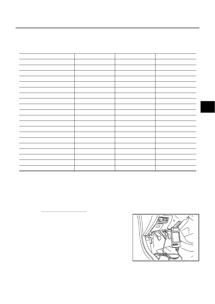
2.
After the ignition switch is turned OFF, connect the CONSULT-II
connector to the vehicle-side data link connector. The data link
connector is on the lower instrument cover).
3.
Start the engine and drive at Approx. 30 km/h (19 MPH) for
approx. 1 minute.
Item
Self-diagnosis
Data monitor
Active test
Wheel sensors
×
×
–
Solenoid valves
×
×
×
Switch-over solenoid valves
×
×
×
Stop lamp switch
×
×
–
Yaw rate sensor
×
×
×
Side G sensor
×
×
×
Press sensor
×
×
×
Steering angle sensor
×
×
×
Actuator relay
×
×
×
Motor relay
×
×
×
ABS warning lamp
–
×
×
Battery voltage
×
×
–
ESP/TCS/ABS C/U
×
–
–
ESP/TCS/ABS actuator motor
×
×
×
CAN communication
×
×
–
Engine speed signal
–
×
–
ESP OFF switch
–
×
–
ESP OFF indicator lamp
–
×
×
SLIP indicator lamp
–
×
×
Throttle angle
–
×
–
MAIA0009E
BRC-64
[ESP/TCS/ABS]
TROUBLE DIAGNOSIS
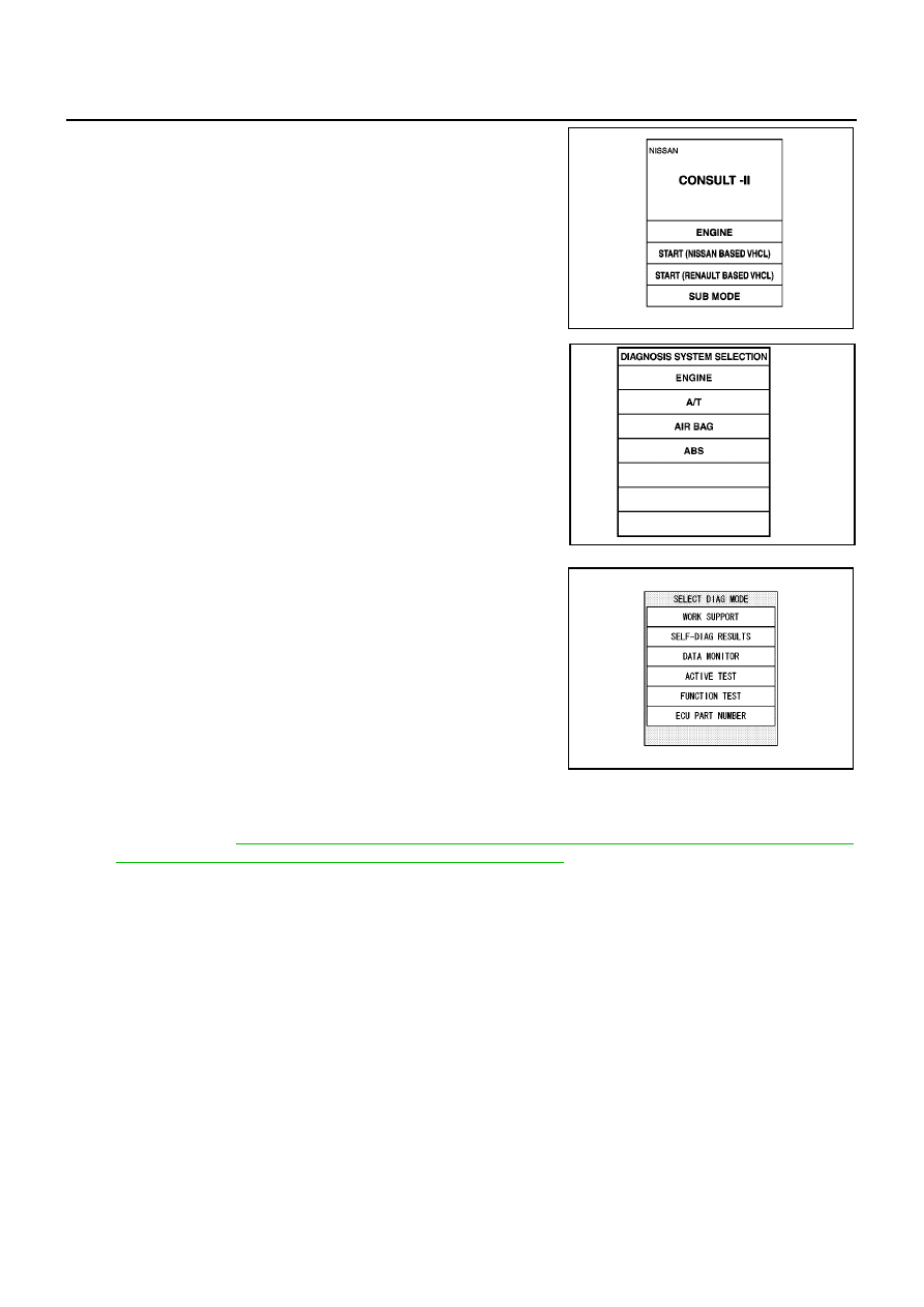
4.
After stopping the vehicle, with the engine still idling, touch “
START
(NISSAN
BASED
VHCL)”,
“ABS”,
“SELF-DIAG
RESULTS” on the CONSULT-II screen in this order.
CAUTION:
Just after starting the engine, or turning the ignition switch
ON, “ABS” may not be displayed on the system selection
screen even if “START (NISSAN BASED VHCL)” is touched.
In this case, start the self-diagnosis again from step 2. If it
cannot be shown after several attempts, the ESP/TCS/
ABS control unit may malfunction. Repair or replace the
control unit.
5.
The self-diagnosis result is displayed. (If necessary, touch “PRINT” to print the self-diagnosis result.)
●
When “NO FAILURE” is shown, check the ABS warning lamp, ESP OFF indicator lamp, SLIP indicator
lamp. Refer to
BRC-75, "PRELIMINARY CHECK 3: (INSPECTION FOR ABS WARNING LAMP,
ESP OFF INDICATOR LAMP, AND SLIP INDICATOR LAMP)"
.
●
CONSULT-II self-diagnosis results are displayed without regard to occurrence timing. In some case, the
later ones (timing value is small) appear on the next screen.
6.
Go to appropriate “Inspection” chart according to “Self-Diagnostic Items to Result Mode” and repair or
replace as necessary.
7.
Start the engine and drive at Approx. 30 km/h (19 MPH) for Approx. 1 minute.
CAUTION:
Check again to make sure that there is NO MALFUNCTION on other parts.
8.
Turn the ignition switch OFF to prepare for erasing the memory.
9.
Start the engine and touch “START (NISSAN BASED VHCL)”, “ABS”, “SELF-DIAG RESULTS” and
“ERASE” on CONSULT-II screen in this order to ease the memory.
CAUTION:
If the memory cannot be erased, go to step 6.
10. Drive the vehicle at Approx. 30 km/h (19 MPH) and check that the ABS warning lamp, ESP OFF indicator
lamp, and SLIP indicator lamp stay off.
CAUTION:
ESP OFF switch is not cancelled.
MBIB0233E
PBR385C
SFIA0365E
Нет комментариевНе стесняйтесь поделиться с нами вашим ценным мнением.
Текст