Nissan Primera P12. Manual — part 138
TROUBLE DIAGNOSIS
BRC-57
[ESP/TCS/ABS]
C
D
E
G
H
I
J
K
L
M
A
B
BRC
MFWA0007E
BRC-58
[ESP/TCS/ABS]
TROUBLE DIAGNOSIS
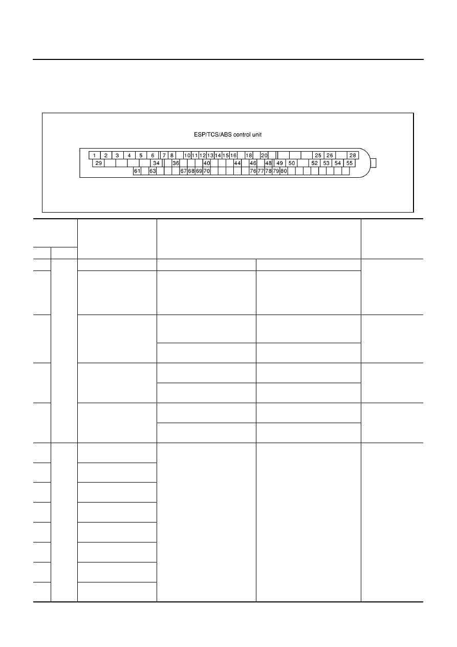
Control Unit Input/Output Signal Standard
EFS002X3
STANDARDS USING A CIRCUIT TESTER AND OSCILLOSCOPE
CAUTION:
Connect the connectors for the ESP/TCS/ABS control unit and actuator, and turn the ignition switch
ON.
SFIA0434E
Measure-
ment termi-
nal
Measuring point
Standard value (Note 1)
(Reference) Check
items for malfunc-
tion
+
–
1
Body
ground
Power supply
Ignition switch ON
Battery voltage (Approx. 12V)
Control unit power
supply circuit
2
Actuator motor relay,
actuator relay power
supply and steering
angle sensor power sup-
ply
Ignition switch ON
Battery voltage (Approx. 12V)
7
Actuator motor relay
Actuator motor being driven
(“Active test” mode with CON-
SULT-II)
Approx. 0V
Actuator motor,
motor relay, and
circuit
Actuator motor while the vehicle
is stopped
Battery voltage (Approx. 12V)
36
Actuator relay
When actuator relay is active.
(the engine running)
Approx. 0V
Actuator relay and
circuit
When actuator relay is inactive.
(Fail-safe, engine starts.)
Battery voltage (Approx. 12V)
20
Actuator motor monitor
When actuator relay is active.
(the engine running)
Battery voltage (Approx. 12V)
Actuator motor
monitor circuit
When actuator relay is inactive.
(Fail-safe, engine starts.)
Approx. 0V
3
Body
ground
Front LH wheel outlet
solenoid valve
Solenoid valve activated
(In “active test” mode of CON-
SULT-II) or actuator relay inac-
tive (in fail-safe mode)
When solenoid valve is inactive
and actuator relay active (when
ignition switch ON)
Approx. 0V
Battery voltage (Approx. 12V)
Solenoid valve and
circuit
4
Rear RH wheel outlet
solenoid valve
5
Front LH wheel inlet
solenoid valve
6
Rear RH wheel inlet
solenoid valve
25
Rear LH wheel outlet
solenoid valve
26
Front RH wheel inlet
solenoid valve
53
Rear LH wheel inlet sole-
noid valve
55
Front RH wheel outlet
solenoid valve
TROUBLE DIAGNOSIS
BRC-59
[ESP/TCS/ABS]
C
D
E
G
H
I
J
K
L
M
A
B
BRC
49
Body
ground
Primary-side ESP
switch-over solenoid
valve 1 (USV)
When switch-over solenoid
valve is active (in “active test”
mode of CONSULT-II)
Or, when actuator relay inactive
(when fail-safe)
When switch-over solenoid
valve is inactive and actuator
relay is active (when ignition
switch ON)
Approx. 0V
Battery voltage (Approx. 12V)
Switch-over sole-
noid valve and cir-
cuit
50
Secondary-side ESP
switch-over solenoid
valve 1 (USV)
52
Secondary-side ESP
switch-over solenoid
valve 2 (HSV)
54
Primary-side ESP
switch-over solenoid
valve 2 (HSV)
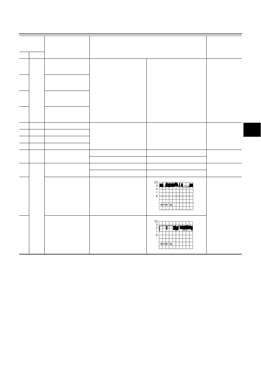
8
10
Front LH wheel sensor
Wheel rotated (Approx. 30 km/h
(19 MPH) (Note 2)
Pulse generation
: Approx. 200 Hz
Wheel sensor and
circuit
11
12
Rear RH wheel sensor
13
14
Rear LH wheel sensor
15
16
Front RH wheel sensor
48
Body
ground
Stop lamp signal
Depress brake pedal.
Battery voltage (Approx. 12V)
Stop lamp switch
and circuit
Release the brake pedal.
Approx. 0V
44
Body
ground
ESP OFF switch
ESP OFF switch is pressed.
Approx. 10V
ESP OFF switch
and circuit
ESP OFF switch is released.
Approx. 12V
61
CAN communication
input/output signal (H)
Ignition switch ON
–
63
CAN communication
input/output signal (L)
Ignition switch ON
Measure-
ment termi-
nal
Measuring point
Standard value (Note 1)
(Reference) Check
items for malfunc-
tion
+
–
PBIA0224J
PBIA0223J
BRC-60
[ESP/TCS/ABS]
TROUBLE DIAGNOSIS
(Note 1): When the standard value is checked using a circuit tester for voltage measurement, the connector terminals should not extend
forcefully.
(Note 2): Check the pressure of the tire in normal condition.
(Note 3): ON/OFF timing of the ABS warning lamp
ON: When the ignition switch is turned ON (before engine start) or a malfunction is detected.
OFF: 2 seconds after the engine started (the system is in normal condition).
(Note 4): ESP OFF indicator lamp ON/OFF timing
ON: When the ignition switch is turned ON (before engine start) or a malfunction is detected, if the ESP OFF switch is ON.
OFF: 2 seconds after the engine started (the system is in normal condition) and ESP OFF switch is OFF.
(Note 5): ON/OFF timing of the SLIP indicator lamp
ON: When the ignition switch is turned ON (before engine start) or a malfunction is detected.
OFF: 2 seconds after the engine started (the system is in normal condition) and the ESP/TCS function is inactive.
Flashing: ESP/TCS function is active during driving.
STANDARDS WITH CONSULT-II
CAUTION:
The displayed item is the data calculated by the control unit, so it may indicate a normal value even if
an output circuit (harness) is open or shorted.
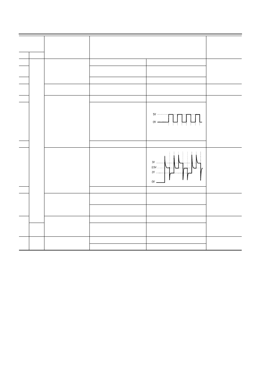
67
Body
ground
Pressure sensor
Ignition switch ON
Approx. 0V
Pressure sensor
and circuit
68
When ignition switch ON and
brake pedal released.
Approx. 0.6V
69
Ignition switch ON
Approx. 0V
18
Side G sensor
Ignition switch ON
Approx. 2.5V
Yaw rate /Side G
sensor and circuit
34
Yaw rate/Side G sensor
Ignition switch ON
Battery voltage (Approx. 12V)
Yaw rate /Side G
sensor and circuit
77
Ignition switch ON
78
Ignition switch ON
Approx. 2.5V
79
Yaw rate sensor
Ignition switch ON
Yaw rate sensor
and circuit
80
Ignition switch ON
Approx. 0V
70
ESP OFF indicator lamp
ESP OFF indicator lamp turns
on (Note 4)
Approx. 0V
ESP OFF warning
lamp and circuit
ESP OFF indicator lamp turns
off (note 4)
Battery voltage (Approx. 12V)
40
Brake fluid level warning
switch
Brake fluid is not enough
Battery voltage (Approx. 12V)
Brake fluid level
warning switch and
circuit
Brake fluid is enough
Approx. 0V
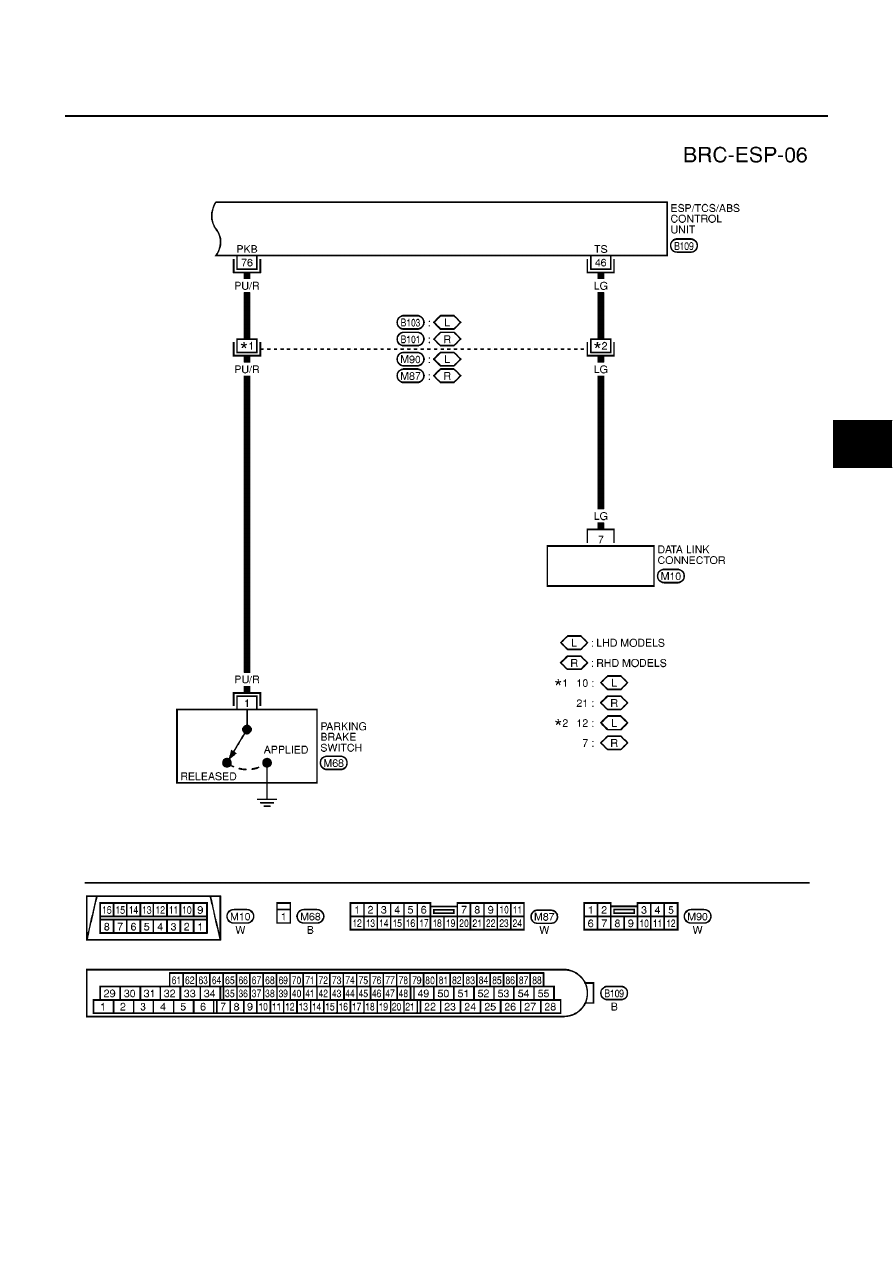
76
Body
ground
Parking brake signal
Apply the parking brake.
Battery voltage (Approx. 12V)
Parking brake
switch and circuit
Release the parking brake.
Approx. 0V
Measure-
ment termi-
nal
Measuring point
Standard value (Note 1)
(Reference) Check
items for malfunc-
tion
+
–
SFIA0150E
SFIA0151E
Нет комментариевНе стесняйтесь поделиться с нами вашим ценным мнением.
Текст