Nissan Primera P12. Manual — part 141

TROUBLE DIAGNOSIS
BRC-69
[ESP/TCS/ABS]
C
D
E
G
H
I
J
K
L
M
A
B
BRC
RR RH OUT SOL
(ON/OFF)
–
×
×
–
Rear RH wheel outlet sole-
noid valve (ON/OFF) status is
displayed.
FR RH IN SOL
(ON/OFF)
–
×
×
–
Front RH wheel inlet solenoid
valve (ON/OFF) status is dis-
played.
FR RH OUT SOL
(ON/OFF)
–
×
×
–
Front RH wheel outlet sole-
noid valve (ON/OFF) status is
displayed.
RR LH IN SOL
(ON/OFF)
–
×
×
–
Rear LH wheel inlet solenoid
valve (ON/OFF) status is dis-
played.
RR LH OUT SOL
(ON/OFF)
–
×
×
–
Rear LH wheel outlet solenoid
valve (ON/OFF) status is dis-
played.
USV [FL-RR]
(ON/OFF)
–
–
×
–
Primary-side switch-over
solenoid valve (ON/OFF) sta-
tus is displayed. (USV)
USV [FR-RL]
(ON/OFF)
–
–
×
–
Secondary-side switch-over
solenoid valve (ON/OFF) sta-
tus is displayed. (USV)
HSV [FL-RR]
(ON/OFF)
–
–
×
–
Primary-side switch-over
solenoid valve (ON/OFF) sta-
tus is displayed. (HSV)
HSV [FR-RL]
(ON/OFF)
–
–
×
–
Secondary-side switch-over
solenoid valve (ON/OFF) sta-
tus is displayed. (HSV)
V/R OUTPUT
(ON/OFF)
–
–
×
–
Actuator relay operation sig-
nal (ON/OFF) status is dis-
played.
M/R OUTPUT
(ON/OFF)
–
–
×
–
Motor relay activation signal
(ON/OFF) status is displayed.
VDC FAIL SIG
(ON/OFF)
–
–
×
–
ESP fail signal (ON/OFF) sta-
tus is displayed.
TCS FAIL SIG
(ON/OFF)
–
–
×
–
TCS fail signal (ON/OFF) sta-
tus is displayed.
ABS FAIL SIG
(ON/OFF)
–
–
×
–
ABS fail signal (ON/OFF) sta-
tus is displayed.
EBD FAIL SIG
(ON/OFF)
–
–
×
–
EBD fail signal (ON/OFF) sta-
tus is displayed.
FLUID LEV SW
(ON/OFF)
–
–
×
–
Brake fluid level warning
switch (ON/OFF) status is dis-
played.
SNOW MODE SW
(ON/OFF)
–
–
×
–
“OFF” is displayed.
BST OPER SIG
(ON/OFF)
–
–
×
–
“OFF” is displayed.
CAN COMM
(OK/NG)
–
–
–
×
CAN communication signal
(OK/NG) status is displayed.
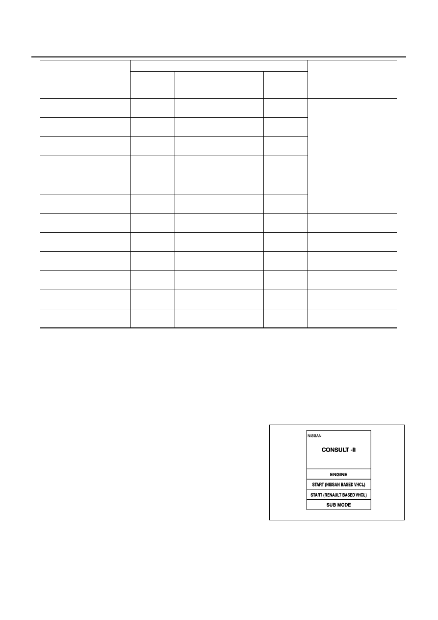
Data Monitor Item (Unit)
Data Monitor item selection
Remarks
ECU INPUT
SIGNALS
MAIN
SIGNALS
SELECTION
FROM
MENU
CAN DIAG
SUPPORT
MNTR
BRC-70
[ESP/TCS/ABS]
TROUBLE DIAGNOSIS
×
: Applicable
–: Not applicable
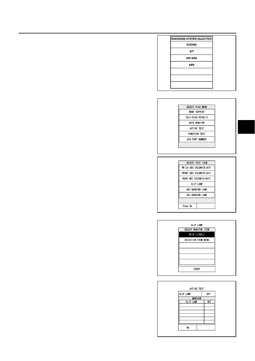
ACTIVE TEST
Procedure
CAUTION:
●
Do not perform active test while driving the vehicle.
●
Make sure that completely bleed air from the brake system.
●
The active test cannot be performed with the ABS warning lamp on.
1.
Connect the CONSULT-II connector to the vehicle-side data link connector and start the engine.
2.
Touch “START (NISSAN BASED VHCL)” on the display.
CAN CIRC 1
(ON/ UNKWN)
–
–
–
×
CAN communication signal
(OK/UNKWN) status is dis-
played.
CAN CIRC 2
(OK/ UNKWN)
–
–
–
×
CAN CIRC 3
(OK/ UNKWN)
–
–
–
×
CAN CIRC 4
(OK/ UNKWN)
–
–
–
×
CAN CIRC 5
(ON / UNKWN)
–
–
–
×
CAN CIRC 6
(ON / UNKWN)
–
–
–
×
M MODE SIG
(ON/OFF)
–
–
×
–
“OFF” is displayed.
OD OFF SW
(ON/OFF)
–
–
×
–
“OFF” is displayed.
EBD SIGNAL
(ON/OFF)
–
–
×
–
EBD operation (ON/OFF) sta-
tus is displayed.
ABS SIGNAL
(ON/OFF)
–
–
×
–
ABS operation (ON/OFF) sta-
tus is displayed.
TCS SIGNAL
(ON/OFF)
–
–
×
–
TCS operation (ON/OFF) sta-
tus is displayed.
VDC SIGNAL
(ON/OFF)
–
–
×
–
ESP operation (ON/OFF) sta-
tus is displayed.
Data Monitor Item (Unit)
Data Monitor item selection
Remarks
ECU INPUT
SIGNALS
MAIN
SIGNALS
SELECTION
FROM
MENU
CAN DIAG
SUPPORT
MNTR
MBIB0233E
TROUBLE DIAGNOSIS
BRC-71
[ESP/TCS/ABS]
C
D
E
G
H
I
J
K
L
M
A
B
BRC
3.
Touch “ABS” and “ACTIVE TEST”.
4.
The test item selection screen is displayed.
5.
Touch necessary test item.
6.
Touch “START” with “MAIN SIGNALS” line inverted.
7.
The active test screen is displayed.
PBR385C
SFIA0365E
SFIA0366E
SFIA0367E
SFIA0368E
BRC-72
[ESP/TCS/ABS]
TROUBLE DIAGNOSIS
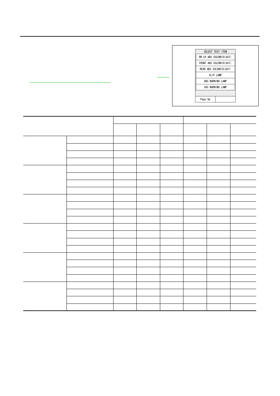
Solenoid Valve
1.
Select each test items without “(ACT)” for the ABS function
active test, and with “(ACT)” for the ESP/TCS function active
test.
2.
Touch “UP”, “KEEP”, and “DOWN” or “UP”, “ACTUATOR UP”,
and “ACTUATOR KEEP”. And check that the solenoid valves
operate as the “Solenoid Valve Operation Chart”. Refer to
72, "Solenoid Valve Operation Chart"
.
Solenoid Valve Operation Chart
*: ON for 1 to 2 seconds after the touch, and then OFF
NOTE:
●
If the active test is performed with the brake pedal depressed, the pedal stroke may be changed. This is a
normal condition.
●
“TEST STOP” is displayed 6 seconds after the operation start.
●
After “TEST STOP” is displayed, to perform the test again, repeat the step 6 of the operation procedure.
ESP OFF Indicator Lamp
Touch “ ON ” and “ OFF” on the “VDC WARNING LAMP” screen to check that ESP OFF indicator lamp oper-
ates as follows.
SFIA0366E
Operation
Without “(ACT)”
With “(ACT)”
UP
KEEP
DOWN
UP
ACTUA-
TOR UP
ACTUA-
TOR KEEP
FR RH SOL
FR RH ABS SOLE-
NOID (ACT)
FR RH IN SOL
OFF
ON
ON
OFF
OFF
OFF
FR RH OUT SOL
OFF
OFF
ON*
OFF
OFF
OFF
USV [FR-RL]
OFF
OFF
OFF
OFF
ON
ON
HSV [FR-RL]
OFF
OFF
OFF
OFF
ON*
OFF
FR LH SOL
FR LH ABS SOLE-
NOID (ACT)
FR LH IN SOL
OFF
ON
ON
OFF
OFF
OFF
FR LH OUT SOL
OFF
OFF
ON*
OFF
OFF
OFF
USV [FL-RR]
OFF
OFF
OFF
OFF
ON
ON
HSV [FL-RR]
OFF
OFF
OFF
OFF
ON*
OFF
RR RH SOL
RR RH ABS SOLE-
NOID (ACT)
RR RH IN SOL
OFF
ON
ON
OFF
OFF
OFF
RR RH OUT SOL
OFF
OFF
ON*
OFF
OFF
OFF
USV [FL-RR]
OFF
OFF
OFF
OFF
ON
ON
HSV [FL-RR]
OFF
OFF
OFF
OFF
ON*
OFF
RR LH SOL
RR LH ABS SOLE-
NOID (ACT)
RR LH IN SOL
OFF
ON
ON
OFF
OFF
OFF
RR LH OUT SOL
OFF
OFF
ON*
OFF
OFF
OFF
USV [FR-RL]
OFF
OFF
OFF
OFF
ON
ON
HSV [FR-RL]
OFF
OFF
OFF
OFF
ON*
OFF
FRONT SOLENOID
FRONT ABS SOLE-
NOID (ACT)
FR RH IN SOL
OFF
ON
ON
OFF
OFF
OFF
FR RH OUT SOL
OFF
OFF
ON
OFF
OFF
OFF
FR LH IN SOL
OFF
ON
ON
OFF
OFF
OFF
FR LH OUT SOL
OFF
OFF
ON
OFF
OFF
OFF
REAR SOLENOID
REAR ABS SOLE-
NOID (ACT)
RR RH IN SOL
OFF
ON
ON
OFF
OFF
OFF
RR RH OUT SOL
OFF
OFF
ON
OFF
OFF
OFF
RR LH IN SOL
OFF
ON
ON
OFF
OFF
OFF
RR LH OUT SOL
OFF
OFF
ON
OFF
OFF
OFF
Нет комментариевНе стесняйтесь поделиться с нами вашим ценным мнением.
Текст