Nissan Primera P12. Manual — part 304

TROUBLE DIAGNOSIS
EC-401
[YD (WITHOUT EURO-OBD)]
C
D
E
F
G
H
I
J
K
L
M
A
EC
MAS AIR/FL SE [V]
×
×
●
The signal voltage of the mass
air flow sensor is displayed.
MAIN INJ WID [msec]
×
●
Indicates the actual fuel injec-
tion pulse width compensated
by ECM according to the input
signals.
PUMP CURRENT [mA]
×
●
Indicates the fuel pump power
supply current from the ECM.
GLOW RLY [ON/OFF]
×
●
The glow relay control condition
(determined by ECM according
to the input signal) is displayed.
COOLING FAN
[LOW/HI/OFF]
×
●
Indicates the control condition of
the cooling fans (determined by
ECM according to the input sig-
nal).
LOW ... Operates at low speed.
HI ... Operates at high speed.
OFF ... Stopped
EGR VOL CON/V [step]
×
●
Indicates the EGR volume con-
trol value computed by the ECM
according to the input signals.
●
The opening becomes larger as
the value increases.
INT/A VOLUME [mg/]
●
The intake air volume computed
from the mass air flow sensor
signal is displayed.
BARO SEN [kPa]
×
×
●
The barometric pressure (deter-
mined by the signal voltage from
the absolute pressure sensor
built into the ECM) is displayed.
INT/M PRES SE [kPa]
●
Turbocharger boost (determined
by the signal voltage from the
turbocharger boost sensor) is
displayed.
CYL COUNT [1/2/3/4]
●
The cylinder being injected is
displayed.
1 ... Cylinder No.1 is injected.
2 ... Cylinder No.2 is injected.
3 ... Cylinder No.3 is injected.
4 ... Cylinder No.4 is injected.
SET SW
[ON/OFF]
×
●
Indicates [ON/OFF] condition
from SET/COAST switch signal.
RESUME/ACC SW
[ON/OFF]
×
●
Indicates [ON/OFF] condition
from RESUME/ACCEL switch
signal.
CANCEL SW
[ON/OFF]
×
●
Indicates [ON/OFF] condition
from CANCEL switch signal.
MAIN SW
[ON/OFF]
×
●
Indicates [ON/OFF] condition
from ON/OFF switch signal.
MONITOR ITEM
ECM
INPUT
SIG-
NAL
MAIN
SIG-
NALS
CAN
DIAG
SUP-
PORT
MNTR
CONDITION
SPECIFICATION

EC-402
[YD (WITHOUT EURO-OBD)]
TROUBLE DIAGNOSIS
NOTE:
Any monitored item that does not match the vehicle being diagnosed is deleted from the display automatically.
ACTIVE TEST MODE
Voltage [V]
Voltage, frequency, duty cycle or
pulse width measured by the
probe.
Only “#” is displayed if item is
unable to be measured.
Figures with “#”s are temporary
ones.
They are the same figures as an
actual piece of data which was
just previously measured. [Hz] or
[%]
Frequency [msec], [Hz] or
[%]
DUTY-HI
DUTY-LOW
PLS WIDTH-HI
PLS WIDTH-LOW
CAN COMM
[OK/NG]
×
●
Indicates the communication
condition of CAN communica-
tion line.
●
These items are not displayed
in “SELECTION FROM MENU”
mode.
CAN CIRC 1
[OK/UNKWN]
×
CAN CIRC 2
[OK/UNKWN]
×
CAN CIRC 3
[OK/UNKWN]
×
CAN CIRC 4
[OK/UNKWN]
×
CAN CIRC 5
[OK/UNKWN]
×
CAN CIRC 6
[OK/UNKWN]
×
CAN CIRC 7
[OK/UNKWN]
×
MONITOR ITEM
ECM
INPUT
SIG-
NAL
MAIN
SIG-
NALS
CAN
DIAG
SUP-
PORT
MNTR
CONDITION
SPECIFICATION
TEST ITEM
CONDITION
JUDGEMENT
CHECK ITEM (REMEDY)
POWER BAL-
ANCE
●
Engine: After warming up, idle the
engine.
●
A/C switch: OFF
●
Shift lever: N
●
Cut off each injector signal one at
a time using CONSULT-II
Engine runs rough or dies.
●
Harness and connectors
●
Compression
●
Fuel injector
COOLING FAN *
●
Ignition switch: ON
●
Operate the cooling fan at LOW,
HI speed and turn OFF using
CONSULT-II.
Cooling fan moves at LOW, HI
speed and stops.
●
Harness and connector
●
Cooling fan motor
●
Cooling fan relay
ENG COOLANT
TEMP
●
Engine: Return to the original
trouble condition
●
Change the engine coolant tem-
perature using CONSULT-II.
If trouble symptom disappears, see
CHECK ITEM.
●
Harness and connectors
●
Engine coolant temperature sen-
sor
●
Fuel injector
GLOW RLY
●
Ignition switch: ON (Engine
stopped)
●
Turn the glow relay ON and OFF
using CONSULT-II and listen to
operating sound.
Glow relay makes the operating
sound.
●
Harness and connector
●
Glow relay
TROUBLE DIAGNOSIS
EC-403
[YD (WITHOUT EURO-OBD)]
C
D
E
F
G
H
I
J
K
L
M
A
EC
*:Leaving cooling fan OFF with CONSULT-II while engine is running may cause the engine to overheat.
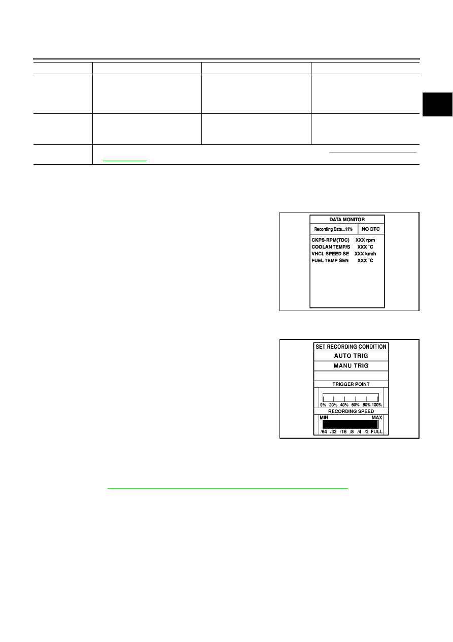
REAL TIME DIAGNOSIS IN DATA MONITOR MODE
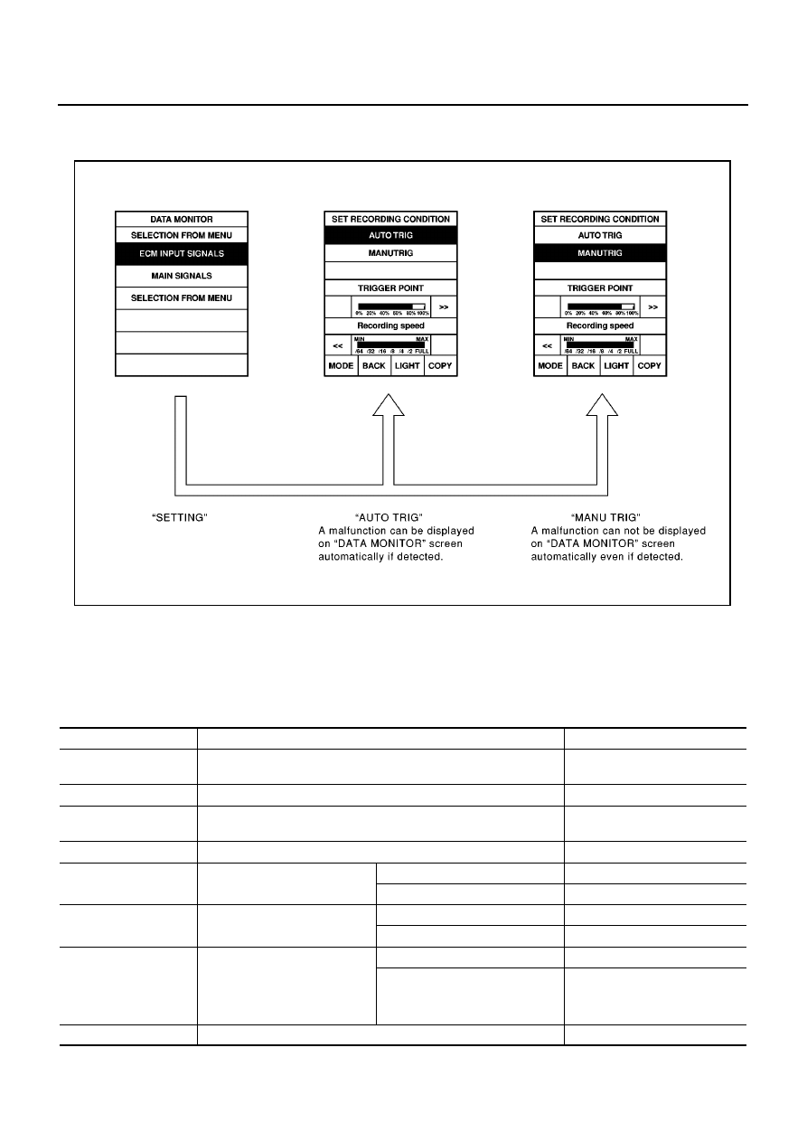
CONSULT-II has two kinds of triggers and they can be selected by touching “SETTING” in “DATA MONITOR”
mode.
1.
“AUTO TRIG” (Automatic trigger):
–
The malfunction will be identified on the CONSULT-II screen in
real time.
In other words, DTC will be displayed if the malfunction is
detected by ECM.
At the moment a malfunction is detected by ECM, “MONITOR”
in “DATA MONITOR” screen is changed to “Recording Data ...
xx%” as shown in the figure, and the data after the malfunction
detection is recorded. Then when the percentage reached
100%, “REAL-TIME DIAG” screen is displayed. If “STOP” is
touched on the screen during “ Recording Data ... xx%”, “REAL-
TIME DIAG” screen is also displayed.
The recording time after the malfunction detection and the recording speed can be changed by “TRIG-
GER POINT” and “Recording Speed”. Refer to CONSULT-II OPERATION MANUAL.
2.
“MANU TRIG” (Manual trigger):
–
DTC will not be displayed automatically on CONSULT-II screen
even though a malfunction is detected by ECM.
DATA MONITOR can be performed continuously even though a
malfunction is detected.
Use these triggers as follows:
1.
“AUTO TRIG”
–
While trying to detect the DTC by performing the DTC Confirma-
tion Procedure, be sure to select to “DATA MONITOR (AUTO
TRIG)” mode. You can confirm the malfunction at the moment it
is detected.
–
While narrowing down the possible causes, CONSULT-II should be set in “DATA MONITOR (AUTO
TRIG)” mode, especially in case the incident is intermittent.
When you are inspecting the circuit by gently shaking (or twisting) the suspicious connectors, components
and harness in the DTC Confirmation Procedure, the moment a malfunction is found the DTC will be dis-
played. Refer to
GI-24, "How to Perform Efficient Diagnosis for an Electrical Incident"
, “INCIDENT SIMU-
LATION TESTS”.
2.
“MANU TRIG”
EGR VOL CONT/
V
●
Ignition switch: ON
●
Change EGR volume control
valve opening step using CON-
SULT-II.
EGR volume control valve makes
an operating sound.
●
Harness and connector
●
EGR volume control valve
PRES REGULA-
TOR
●
Ignition switch: ON
●
Change fuel rail pressure using
CONSULT-II
Fuel leaks.
●
Fuel line
●
Fuel pressure relief valve
PUMP LEANT
CLEAR
●
This mode is used for performing Fuel Pump Learning Value Clearing. Refer to
.
TEST ITEM
CONDITION
JUDGEMENT
CHECK ITEM (REMEDY)
PBIB0480E
SEF707X
EC-404
[YD (WITHOUT EURO-OBD)]
TROUBLE DIAGNOSIS
–
If the malfunction is displayed as soon as “DATA MONITOR” is selected, reset CONSULT-II to “MANU
TRIG”. By selecting “MANU TRIG” you can monitor and store the data. The data can be utilized for further
diagnosis, such as a comparison with the value for the normal operating condition.
FUNCTION TEST
This mode is used to inform customers of their vehicle condition of periodic maintenance.
CONSULT-II Reference Value in Data Monitor Mode
EBS0153I
Remarks:
●
Specification data are reference values.
●
Specification data are output/input values which are detected or supplied by the ECM at the connector.
* Specification data may not be directly related to their components signals/values/operations.
SEF720X
MONITOR ITEM
CONDITION
SPECIFICATION
CKPS-RPM (TDC)
●
Run engine and compare CONSULT-II value with the tachometer
indication.
Almost the same speed as the
tachometer indication
COOLAN TEMP/S
●
Engine: After warming up
More than 70
°
C (158
°
F)
VHCL SPEED SE
●
Turn drive wheels and compare CONSULT-II value with the speed-
ometer indication
Almost the same speed as the
speedometer indication
FUEL TEMP SEN
●
Engine: After warming up
More than 40
°
C (104
°
F)
ACCEL POS SEN*
●
Ignition switch: ON
(Engine stopped)
Accelerator pedal: fully released
0.2 - 0.7V
Accelerator pedal: fully depressed
3.9 - 4.9V
ACCEL SEN 2*
●
Ignition switch: ON
(Engine stopped)
Accelerator pedal: fully released
0.1 - 0.4V
Accelerator pedal: fully depressed
1.9 - 2.4V
MAS AIR/FL SE*
●
Engine: After warming up
●
Air conditioner switch: OFF
●
Shift lever: Neutral position
●
No-load
Idle
1.5 - 2.0V
2,000 rpm
2.2 - 2.7V
BATTERY VOLT
●
Ignition switch: ON (Engine stopped)
11 - 14V
Нет комментариевНе стесняйтесь поделиться с нами вашим ценным мнением.
Текст