Nissan Primera P12. Manual — part 303
TROUBLE DIAGNOSIS
EC-397
[YD (WITHOUT EURO-OBD)]
C
D
E
F
G
H
I
J
K
L
M
A
EC
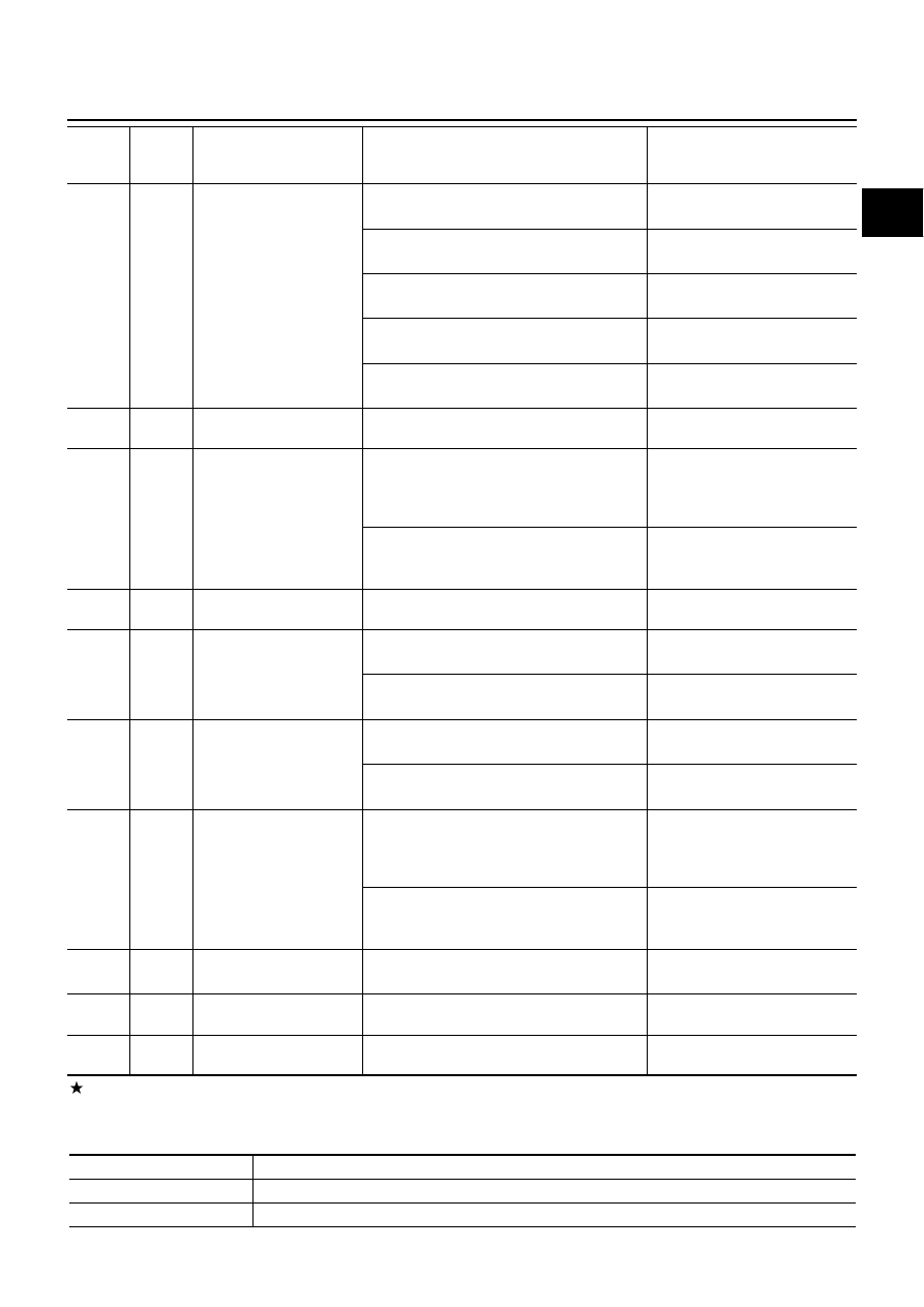
: Average voltage for pulse signal (Actual pulse signal can be confirmed by oscilloscope.)
CONSULT-II Function
EBS0153G
FUNCTION
102
PU
ASCD steering switch
[Ignition switch ON]
●
ASCD steering switch is OFF
Approximately 4.3V
[Ignition switch ON]
●
ON/OFF switch is ON.
Approximately 0.3V
[Ignition switch ON]
●
CANCEL switch is ON.
Approximately 1.3V
[Ignition switch ON]
●
SET/COAST switch is ON.
Approximately 2.3V
[Ignition switch ON]
●
RESUME/ACCEL switch is ON.
Approximately 3.3V
103
B
ASCD steering switch
ground
[Ignition switch ON]
Approximately 0.3V
105
G
ECM relay (self-shutoff)
[Ignition switch ON]
[Ignition switch OFF]
●
For a few seconds after turning ignition
switch OFF
Approximately 1.2V
[Ignition switch OFF]
●
More than a few seconds after turning igni-
tion switch OFF
BATTERY VOLTAGE
(11 - 14V)
107
108
W/R
W/R
Ignition switch
[Ignition switch ON]
BATTERY VOLTAGE
(11 - 14V)
110
G/OR
Park/Neutral position
switch
[Ignition switch ON]
●
Gear position is Neutral
Approximately 0V
[Ignition switch ON]
●
Except the above gear position
BATTERY VOLTAGE
(11 - 14V)
111
R/B
Power steering pressure
switch
[Engine is running]
●
Steering wheel is being turned
Approximately 0V
[Engine is running]
●
Steering wheel is not being turned
BATTERY VOLTAGE
(11 - 14V)
113
G
ECM relay (self-shutoff)
[Ignition switch ON]
[Ignition switch OFF]
●
For a few seconds after turning ignition
switch OFF
Approximately 1.2V
[Ignition switch OFF]
●
More than a few seconds after turning igni-
tion switch OFF
BATTERY VOLTAGE
(11 - 14V)
114
B
ECM ground
[Engine is running]
●
Idle speed
Approximately 0V
119
120
R
R
Power supply for ECM
[Ignition switch ON]
BATTERY VOLTAGE
(11 - 14V)
121
W/L
Power supply for ECM
(Back-up)
[Ignition switch OFF]
BATTERY VOLTAGE
(11 - 14V)
TERMI-
NAL
NO.
WIRE
COLOR
ITEM
CONDITION
DATA
(DC Voltage and Pulse Signal)
Diagnostic test mode
Function
Self-diagnostic results
Self-diagnostic results such as DTC and freeze frame data can be read and erased quickly.*
Data monitor
Input/Output data in the ECM can be read.
EC-398
[YD (WITHOUT EURO-OBD)]
TROUBLE DIAGNOSIS
*: The following emission-related diagnostic information is cleared when the ECM memory is erased.
●
Diagnostic trouble codes
●
Freeze frame data
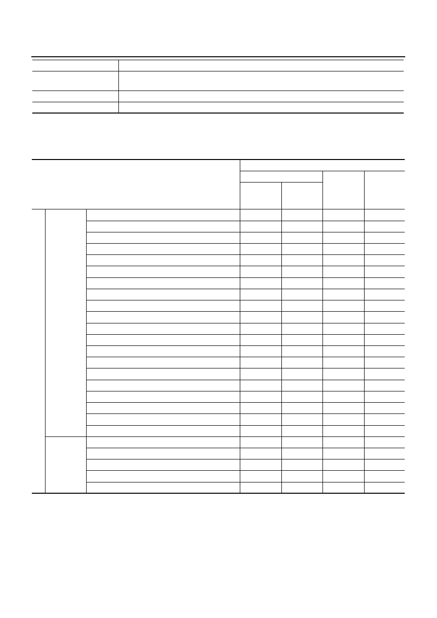
ENGINE CONTROL COMPONENT PARTS/CONTROL SYSTEMS APPLICATION
X: Applicable
Active test
Diagnostic Test Mode in which CONSULT-II drives some actuators apart from the ECMs and also
shifts some parameters in a specified range.
Function test
This mode is used to inform customers when their vehicle condition requires periodic maintenance.
ECM part number
ECM part number can be read.
Diagnostic test mode
Function
Item
DIAGNOSTIC TEST MODE
SELF-DIAG RESULTS
DATA MON-
ITOR
ACTIVE
TEST
DTC
FREEZE
FRAME
DATA
ENGI
NE
CONTROL
C
OMPONENT
P
ARTS
INPUT
Crankshaft position sensor
×
×
×
Camshaft position sensor
×
Engine coolant temperature sensor
×
×
×
×
Vehicle speed sensor
×
×
×
Fuel pump temperature sensor
×
×
Accelerator pedal position sensor 1
×
×
Accelerator pedal position sensor 2
×
×
Fuel rail pressure sensor
×
×
Mass air flow sensor
×
×
Intake air temperature sensor
×
Turbocharger boost sensor
×
×
×
Battery voltage
×
×
Park/neutral position (PNP) switch
×
Power steering pressure switch
×
Stop lamp switch
×
×
Barometric pressure sensor (built-into ECM)
×
×
Fuel injector adjustment resistor
×
ASCD steering switch
×
×
ASCD brake switch
×
×
ASCD clutch switch
×
×
OUTPUT
Fuel pump
×
×
×
Fuel injector
×
×
×
Glow relay
×
×
Cooling fan relay
×
×
×
EGR volume control valve
×
×
TROUBLE DIAGNOSIS
EC-399
[YD (WITHOUT EURO-OBD)]
C
D
E
F
G
H
I
J
K
L
M
A
EC
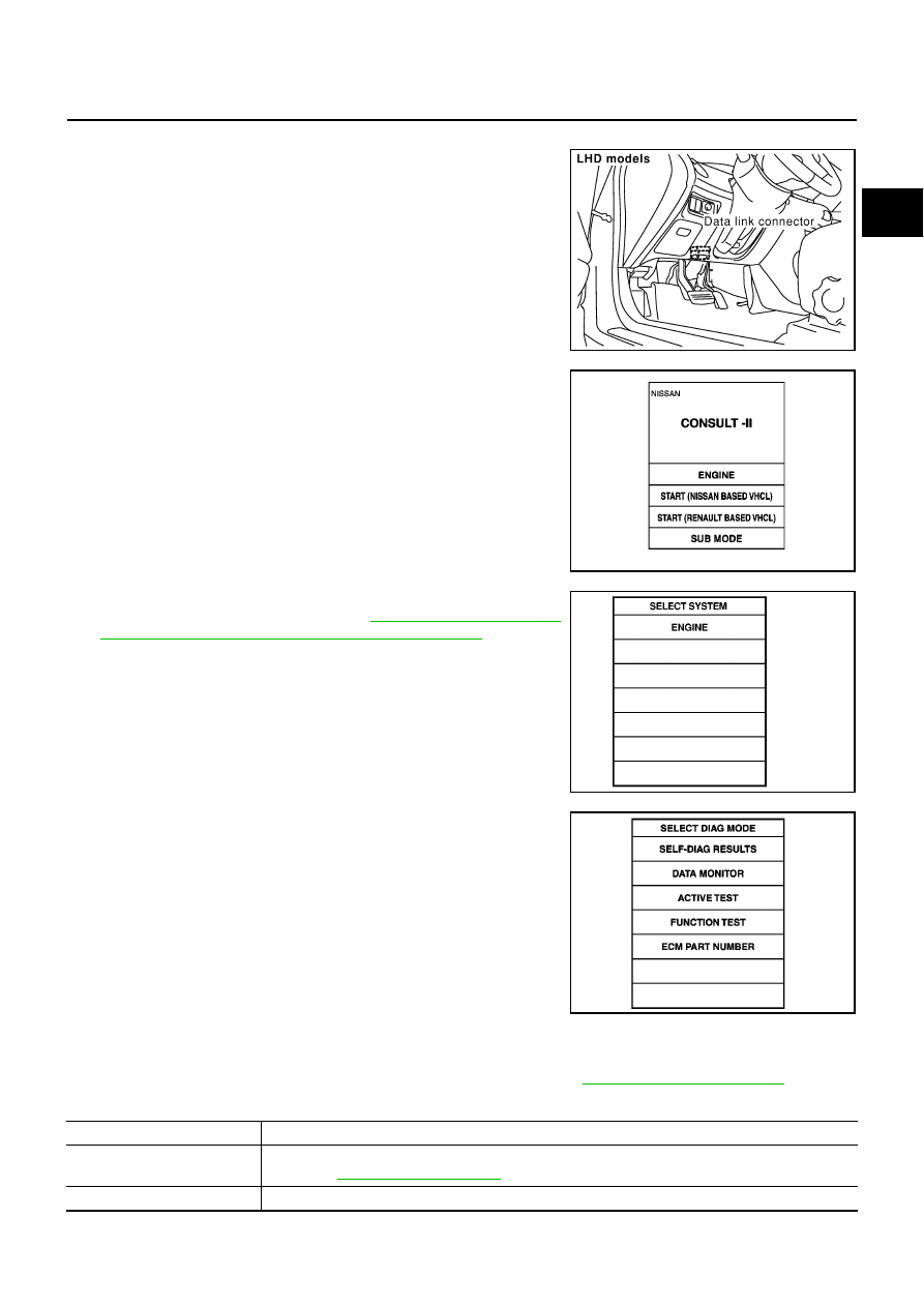
INSPECTION PROCEDURE
1.
Turn ignition switch OFF.
2.
Connect CONSULT-II to data link connector, which is located
under the driver side dash panel.
3.
Turn ignition switch ON.
4.
Touch “START (NISSAN BASED VHCL)”.
5.
Touch “ENGINE”.
If “ENGINE” is not indicated, go to
Link Connector (DLC) Circuit/For YD Engine Models"
.
6.
Perform each diagnostic test mode according to each service
procedure.
For further information, see the CONSULT-II Operation Manual.
SELF-DIAGNOSTIC MODE
Self Diagnostic Item
Regarding items detected in “SELF-DIAG RESULTS” mode, refer to —
.
Freeze Frame Data
MBIB0156E
MBIB0233E
SEF995X
PBIB0410E
Freeze frame data item
Description
DIAG TROUBLE CODE
[PXXXX]
●
The engine control component part/control system has a trouble code, it is displayed as “PXXXX”.
(Refer to
.)
CAL/LD VALUE [%]
●
The calculated load value at the moment a malfunction is detected is displayed.

EC-400
[YD (WITHOUT EURO-OBD)]
TROUBLE DIAGNOSIS
DATA MONITOR MODE
COOLANT TEMP [
°
C] or [
°
F]
●
The engine coolant temperature at the moment a malfunction is detected is displayed.
ENGINE SPEED [rpm]
●
The engine speed at the moment a malfunction is detected is displayed.
VEHICL SPEED [km/h] or
[mph]
●
The vehicle speed at the moment a malfunction is detected is displayed.
INT MANI PRES [kPa]
●
The intake manifold pressure at the moment a malfunction is detected is displayed.
Freeze frame data item
Description
MONITOR ITEM
ECM
INPUT
SIG-
NAL
MAIN
SIG-
NALS
CAN
DIAG
SUP-
PORT
MNTR
CONDITION
SPECIFICATION
CKPS·RPM (TDC) [rpm]
×
×
●
The engine speed computed
from the crankshaft position
sensor signal is displayed.
COOLAN TEMP/S
[
°
C] or [
°
F]
×
×
●
The engine coolant tempera-
ture (determined by the signal
voltage of the engine coolant
temperature sensor) is dis-
played.
When the engine coolant temper-
ature circuit is open or short, ECM
enters fail-safe mode. The engine
coolant temperature determined
by the ECM is displayed.
VHCL SPEED SE
[km/h] or [mph]
×
×
●
The vehicle speed computed
form the vehicle speed sensor
signal is displayed.
FUEL TEMP SEN
[
°
C] or [
°
F]
×
×
●
The fuel temperature (deter-
mined by the signal voltage of
the fuel pump temperature sen-
sor) is displayed.
ACCEL POS SEN [V]
×
×
●
The accelerator pedal position
sensor 1 signal voltage is dis-
played.
ACCEL SEN 2 [V]
×
×
●
The accelerator pedal position
sensor 2 signal voltage is dis-
played.
ACT CR PRESS [MPa]
×
×
●
The Fuel rail pressure (deter-
mined by the signal voltage of
the fuel rail pressure sensor) is
displayed.
BATTERY VOLT [V]
×
×
●
The power supply voltage of
ECM is displayed.
P/N POSI SW [ON/OFF]
×
×
●
Indicates [ON/OFF] condition
from the park/neutral position
switch signal.
START SIGNAL [ON/OFF]
×
×
●
indicates [ON/OFF] condition
from the starter signal.
PW/ST SIGNAL [ON/OFF]
×
●
indicates [ON/OFF] condition
from the power steering pres-
sure switch signal.
[OFF] is always displayed for
models without power steering
pressure switch.
BRAKE SW [ON/OFF]
×
×
●
indicates [ON/OFF] condition
from the stop lamp switch sig-
nal.
BRAKE SW2 [ON/OFF]
×
×
●
indicates [ON/OFF] condition
from the ASCD brake switch
and ASCD clutch switch signal.
IGN SW [ON/OFF]
×
×
●
Indicates [ON/OFF] condition
from ignition switch signal.
Нет комментариевНе стесняйтесь поделиться с нами вашим ценным мнением.
Текст