Nissan Primera P12. Manual — part 523
LAN-4
[CAN]
PRECAUTIONS
[CAN]
PRECAUTIONS
PFP:00001
Precautions for Supplemental Restraint System (SRS) “AIR BAG” and “SEAT
BELT PRE-TENSIONER”
EKS009QJ
The Supplemental Restraint System such as “AIR BAG” and “SEAT BELT PRE-TENSIONER”, used along
with a front seat belt, helps to reduce the risk or severity of injury to the driver and front passenger for certain
types of collision. Information necessary to service the system safely is included in the SRS and SB section of
this Service Manual.
WARNING:
●
To avoid rendering the SRS inoperative, which could increase the risk of personal injury or death
in the event of a collision which would result in air bag inflation, all maintenance must be per-
formed by an authorized NISSAN/INFINITI dealer.
●
Improper maintenance, including incorrect removal and installation of the SRS, can lead to per-
sonal injury caused by unintentional activation of the system. For removal of Spiral Cable and Air
Bag Module, see the SRS section.
●
Do not use electrical test equipment on any circuit related to the SRS unless instructed to in this
Service Manual. SRS wiring harnesses can be identified by yellow and/or orange harnesses or
harness connectors.
Precautions For Trouble Diagnosis
EKS009QK
CAN SYSTEM
●
Do not apply voltage of 7.0V or higher to the measurement terminals.
●
Use the tester with its open terminal voltage being 7.0V or less.
●
Be sure to turn ignition switch off and disconnect negative battery cable before checking the circuit.
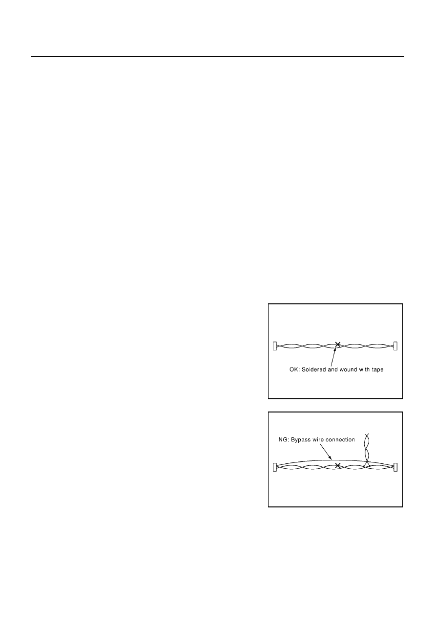
Precautions For Harness Repair
EKS009QL
CAN SYSTEM
●
Solder the repaired parts, and wrap with tape. [Frays of twisted
line must be within 110 mm (4.33 in)]
●
Do not perform bypass wire connections for the repair
parts.(The spliced wire will become separated and the charac-
teristics of twisted line will be lost.)
PKIA0306E
PKIA0307E
CAN COMMUNICATION
LAN-5
[CAN]
C
D
E
F
G
H
I
J
L
M
A
B
LAN
CAN COMMUNICATION
PFP:23710
System Description
EKS009QM
CAN (Controller Area Network) is a serial communication line for real time application. It is an on-vehicle mul-
tiplex communication line with high data communication speed and excellent error detection ability. Many elec-
tronic control units are equipped onto a vehicle, and each control unit shares information and links with other
control units during operation (not independent). In CAN communication, control units are connected with 2
communication lines (CAN H line, CAN L line) allowing a high rate of information transmission with less wiring.
Each control unit transmits/receives data but selectively reads required data only.
CAN Communication Unit
EKS009QN
Go to CAN system, when selecting your car model from the following table.
×
:Applicable
Body type
Sedan/Wagon/Hatch back
Axle
2WD
Engine
YD22DDTi
F9Q
Transmission
M/T
Brake control
ESP
ABS
ESP
ABS
CAN communication unit
ECM
×
×
×
×
×
×
×
×
ESP/TCS/ABS control unit
×
×
×
×
ABS actuator and electric
unit (control unit)
×
×
×
×
Data link connector
×
×
×
×
×
×
×
×
Tyre pressure monitoring
control unit
×
×
×
×
Steering angle sensor
×
×
×
×
Smart entrance control unit
×
×
×
×
×
×
×
×
Combination meter
×
×
×
×
×
×
×
×
Can communication type
Can system
trouble diagno-
sis
LHD
models
RHD
models
-
-
-
-
LAN-6
[CAN]
CAN COMMUNICATION
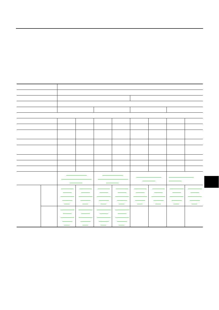
TYPE 21,TYPE22/TYPE29, TYPE30
System diagram
●
LHD models (Type21, Type22)
●
RHD models (Type29, Type30)
Input/output signal chart
T: Transmit R: Receive
SKIA1524E
SKIA1538E
Signals
ECM
ESP/ TCS /
ABS control
unit
Steering
angle sensor
Smart
entrance
control unit
Tyre pres-
sure monitor-
ing control
unit
Combination
meter
Engine speed signal
T
R
R
Accelerator pedal position signal
T
R
Steering angle sensor signal
R
T
Air conditioner switch signal
R
T
MI signal
T
R
Glow indicator lamp signal
T
R
Engine coolant temperature signal
T
R
Fuel consumption signal
T
R
Vehicle speed signal
T
R
R
R
T
Seat belt reminder signal
R
T
Lighting switch position signal
T
R
Flashing indicator signal
T
R
Engine cooling fan speed signal
T
R
Child lock indicator signal
T
R
Door switches state signal
T
R
A/C compressor signal
T
R
Tyre pressure signal
T
R
ASCD SET lamp signal
T
R
ASCD CRUISE lamp signal
T
R
CAN COMMUNICATION
LAN-7
[CAN]
C
D
E
F
G
H
I
J
L
M
A
B
LAN
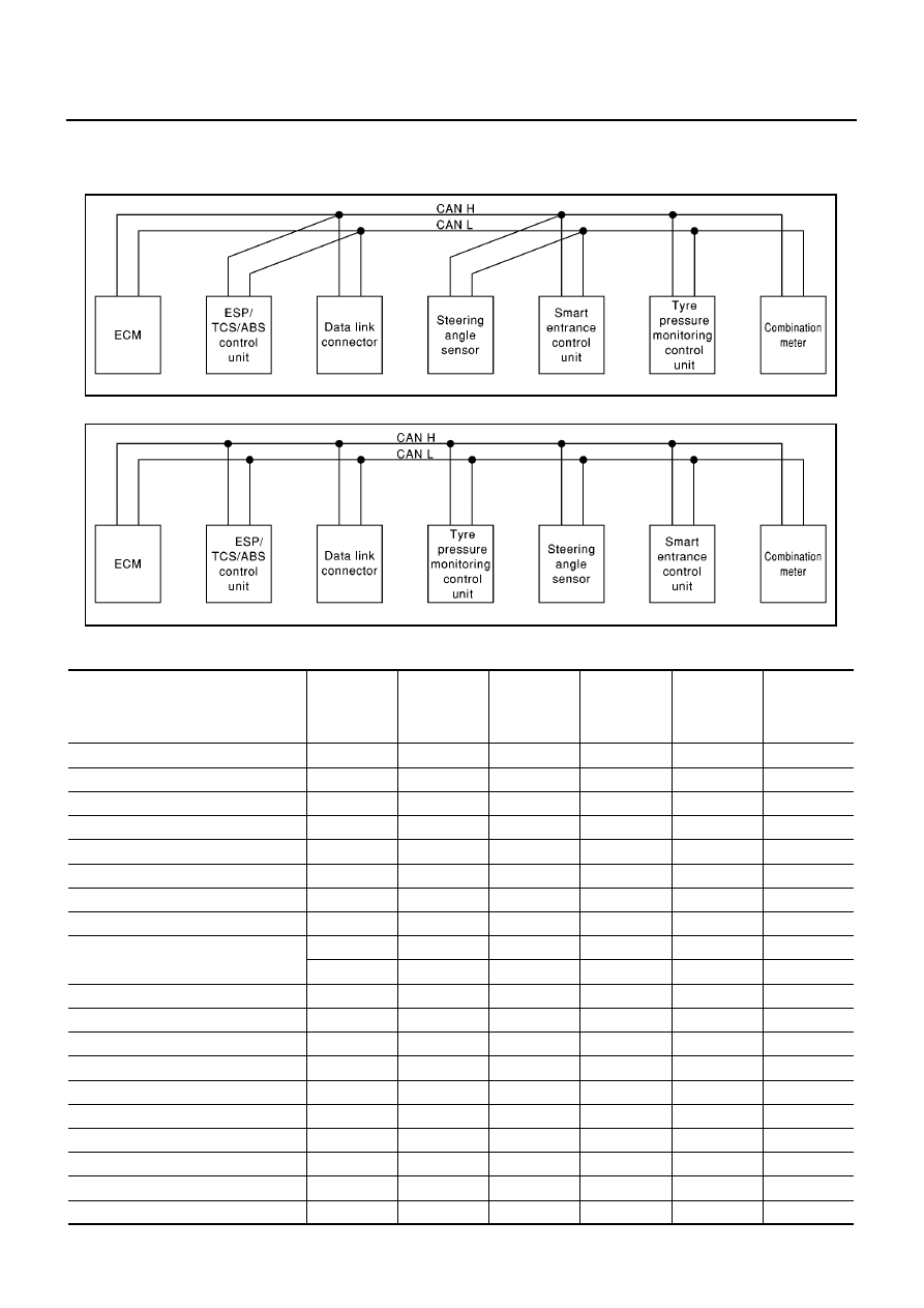
TYPE 23,TYPE24/TYPE31, TYPE32
System diagram
●
LHD models (Type23, Type24)
●
RHD models (Type31, Type32)
Input/output signal chart
T: Transmit R: Receive
SKIA1525E
SKIA1539E
Signals
ECM
ABS actuator
and electric
unit (control
unit)
Smart entrance
control unit
Tyre pressure
monitoring
control unit
Combination
meter
Engine speed signal
T
R
Air conditioner switch signal
R
T
MI signal
T
R
Glow indicator lamp signal
*1
T
R
Engine coolant temperature signal
T
R
Fuel consumption signal
T
R
Vehicle speed signal
T
R
R
R
T
Seat belt reminder signal
R
T
Lighting switch position signal
T
R
Flashing indicator signal
T
R
Engine cooling fan speed signal
T
R
Child lock indicator signal
T
R
Door switches state signal
T
R
A/C compressor signal
T
R
Tyre pressure signal
T
R
ASCD SET lamp signal
T
R
ASCD CRUISE lamp signal
T
R
Нет комментариевНе стесняйтесь поделиться с нами вашим ценным мнением.
Текст