Nissan Primera P12. Manual — part 524
LAN-8
[CAN]
CAN COMMUNICATION
TYPE 25/TYPE26
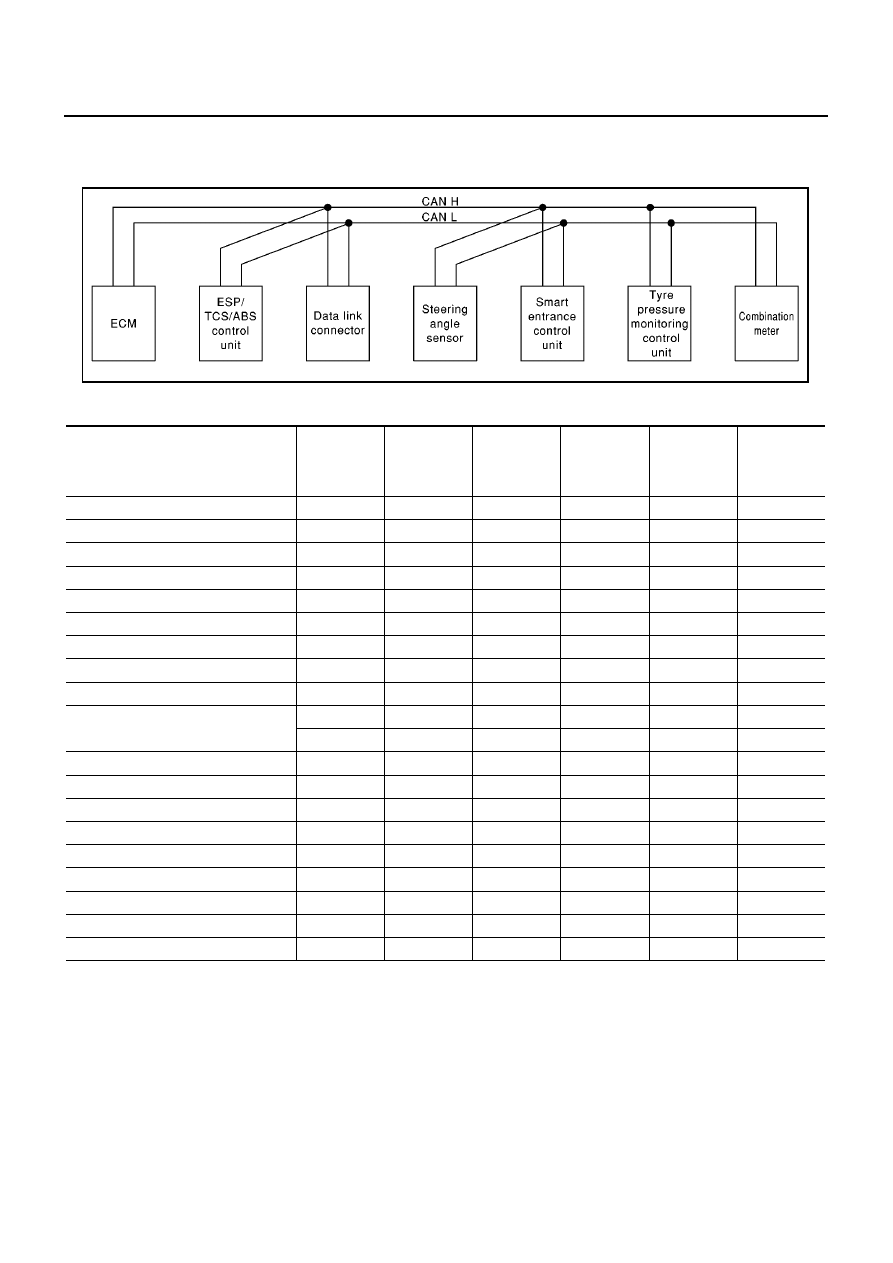
System diagram
LHD models (Type25, Type26)
Input/output signal chart
T: Transmit R: Receive
SKIA1524E
Signals
ECM
ESP/ TCS /
ABS control
unit
Steering
angle sensor
Smart
entrance
control unit
Tyre pres-
sure monitor-
ing control
unit
Combination
meter
Engine speed signal
T
R
R
Accelerator pedal position signal
T
R
ESP operation signal
R
T
TCS operation signal
R
T
ABS operation signal
R
T
Steering angle sensor signal
R
T
MI signal
T
R
Engine coolant temperature signal
T
R
Fuel consumption signal
T
R
Vehicle speed signal
R
T
R
R
T
Seat belt reminder signal
R
T
Lighting switch position signal
T
R
Flashing indicator signal
T
R
Engine cooling fan speed signal
T
R
Child lock indicator signal
T
R
Door switches state signal
T
R
A/C compressor signal
T
R
Glow indicator lamp signal
T
R
Tyre pressure signal
T
R
CAN COMMUNICATION
LAN-9
[CAN]
C
D
E
F
G
H
I
J
L
M
A
B
LAN
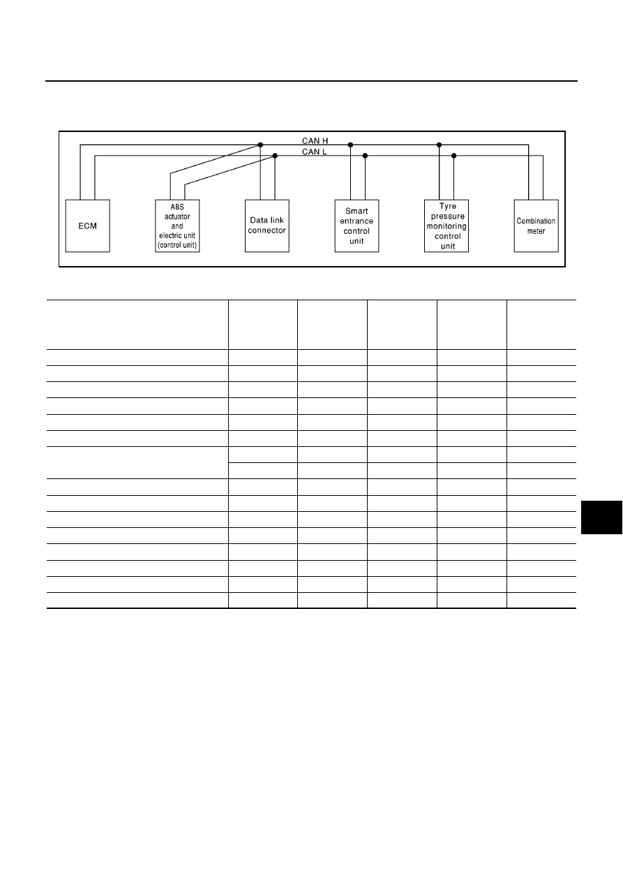
TYPE 27/TYPE28
System diagram
LHD models (Type27, Type28)
Input/output signal chart
T: Transmit R: Receive
SKIA1525E
Signals
ECM
ABS actuator
and electric
unit (control
unit)
Smart entrance
control unit
Tyre pressure
monitoring
control unit
Combination
meter
Engine speed signal
T
R
ABS operation signal
R
T
MI signal
T
R
Glow indicator lamp signal
T
R
Engine coolant temperature signal
T
R
Fuel consumption signal
T
R
Vehicle speed signal
R
T
R
R
T
Seat belt reminder signal
R
T
Lighting switch position signal
T
R
Flashing indicator signal
T
R
Engine cooling fan speed signal
T
R
Child lock indicator signal
T
R
Door switches state signal
T
R
A/C compressor signal
T
R
Tyre pressure signal
T
R
LAN-10
[CAN]
CAN SYSTEM (TYPE 21)
CAN SYSTEM (TYPE 21)
PFP:23710
System Description
EKS00AQ1
CAN (Controller Area Network) is a serial communication line for real time application. It is an on-vehicle mul-
tiplex communication line with high data communication speed and excellent error detection ability. Many elec-
tronic control units are equipped onto a vehicle, and each control unit shares information and links with other
control units during operation (not independent). In CAN communication, control units are connected with 2
communication lines (CAN H line, CAN L line) allowing a high rate of information transmission with less wiring.
Each control unit transmits/receives data but selectively reads required data only.
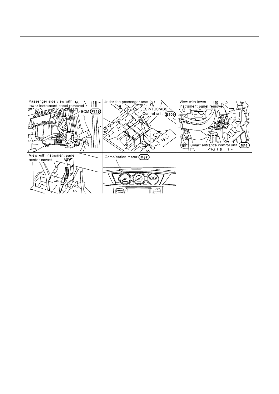
Component Parts and Harness Connector Location
EKS00AQ2
MKIB0603E
CAN SYSTEM (TYPE 21)
LAN-11
[CAN]
C
D
E
F
G
H
I
J
L
M
A
B
LAN
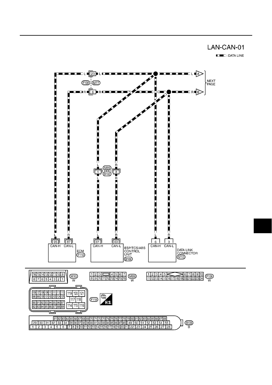
Wiring Diagram — CAN —
EKS00AQ3
MKWA1715E
Нет комментариевНе стесняйтесь поделиться с нами вашим ценным мнением.
Текст