Nissan Primera P12. Manual — part 322
DTC P0217 ENGINE OVER TEMPERATURE
EC-473
[YD (WITHOUT EURO-OBD)]
C
D
E
F
G
H
I
J
K
L
M
A
EC
2.
DETECT MALFUNCTIONING PART
Check the following.
●
Fuse block (J/B) connector E106
●
Harness for open or short between cooling fan relays-2, -4 and fuse
>> Repair open circuit or short to ground or short to power in harness or connectors.
3.
CHECK COOLING FAN RELAY GROUND CIRCUIT FOR OPEN AND SHORT
1.
Turn ignition switch OFF.
2.
Check harness continuity between cooling fan relay-2 terminal 5 and ground, cooling fan relay-4 terminal
5 and ground.
Refer to Wiring Diagram.
3.
Also check harness for short to power.
OK or NG
OK
>> GO TO 4.
NG
>> Repair open circuit or short to power in harness or connectors.
4.
CHECK COOLING FAN MOTOR OUTPUT SIGNAL CIRCUIT FOR OPEN AND SHORT
1.
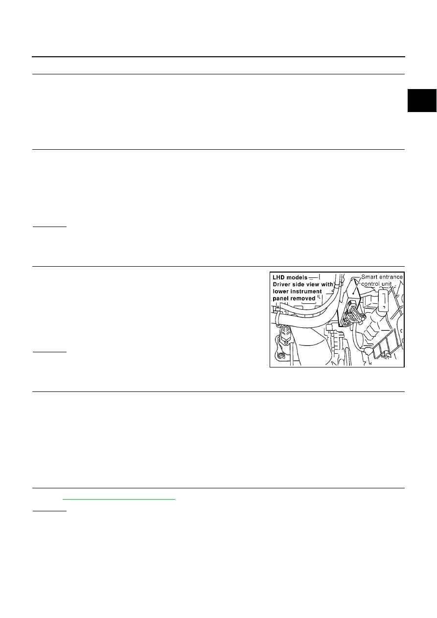
Disconnect smart entrance control unit harness connector.
2.
Check harness continuity between cooling fan relay-2 terminal 2
and smart entrance control unit terminal 32, cooling fan relay-4
terminal 2 and smart entrance control unit terminal 32.
Refer to Wiring Diagram.
3.
Also check harness for short to ground and short to power.
OK or NG
OK
>> GO TO 6.
NG
>> GO TO 5.
5.
DETECT MALFUNCTIONING PART
Check the following.
●
Harness connectors E123, M17 (LHD models)
●
Harness connectors E110, M94 (RHD models)
●
Harness for open or short between cooling fan relay-2 and smart entrance control unit
●
Harness for open or short between cooling fan relay-4 and smart entrance control unit
>> Repair open circuit or short to ground or short to power in harness or connectors.
6.
CHECK COOLING FAN RELAYS-2 AND -4
Refer to
EC-477, "Component Inspection"
.
OK or NG
OK
>> GO TO 7.
NG
>> Replace cooling fan relays.
Continuity should exist.
Continuity should exist.
MBIB0173E
EC-474
[YD (WITHOUT EURO-OBD)]
DTC P0217 ENGINE OVER TEMPERATURE
7.
CHECK SMART ENTRANCE CONTROL UNIT
Refer to
.
OK or NG
OK
>> GO TO 8.
NG
>> Replace smart entrance control unit.
8.
CHECK INTERMITTENT INCIDENT
Perform
EC-408, "TROUBLE DIAGNOSIS FOR INTERMITTENT INCIDENT"
.
>> INSPECTION END
PROCEDURE C
1.
CHECK COOLING FAN MOTOR-2 POWER SUPPLY CIRCUIT
1.
Turn ignition switch OFF.
2.
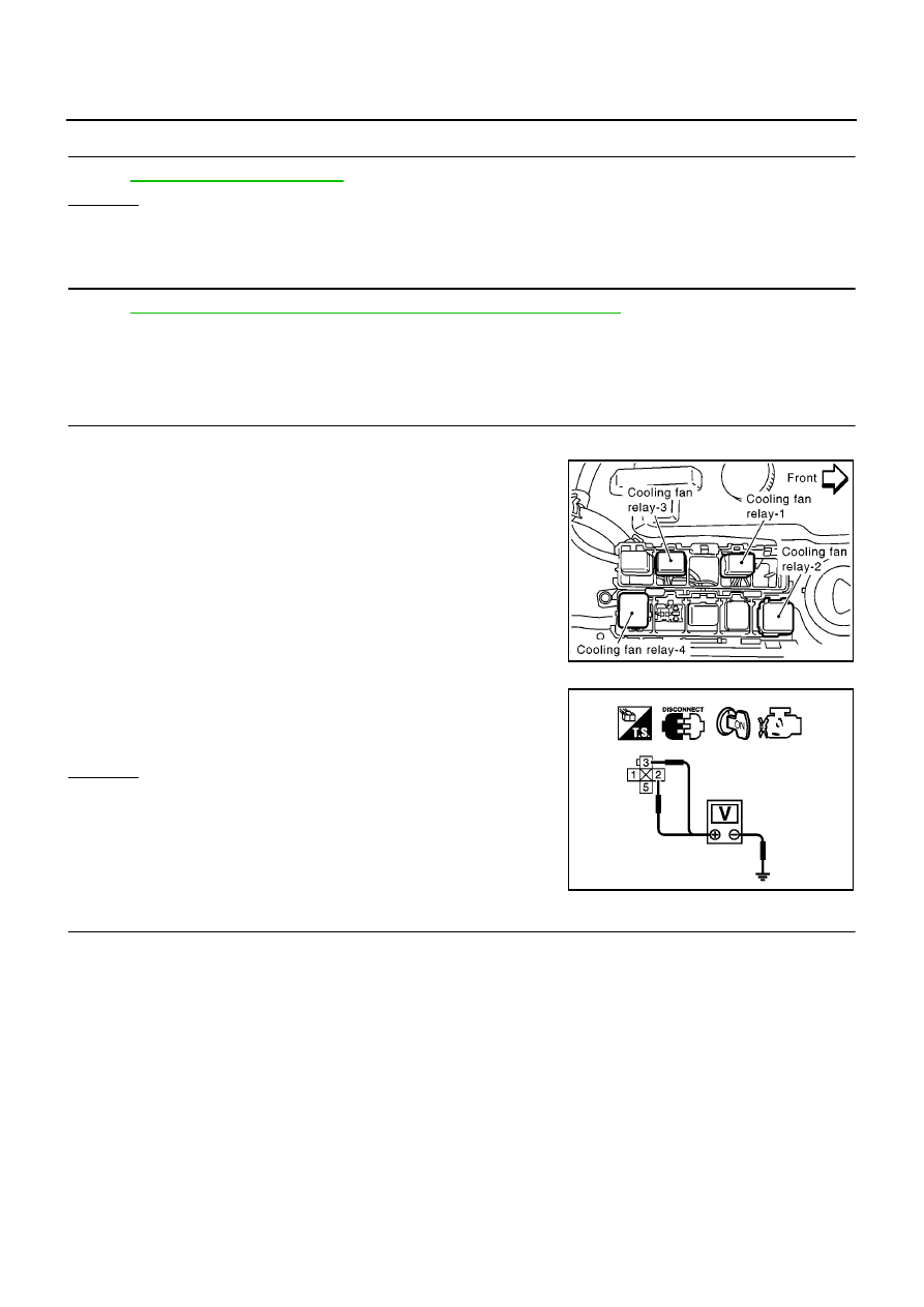
Disconnect cooling fan relay-3.
3.
Turn ignition switch ON.
4.
Check voltage between cooling fan relay-3 terminals 2, 3 and
ground with CONSULT-II or tester.
OK or NG
OK
>> GO TO 3.
NG
>> GO TO 2.
2.
DETECT MALFUNCTIONING PART
Check the following.
●
Fuse block (J/B) connector E106
●
40A fusible link
●
Harness for open or short between cooling fan relay-3 and fuse
●
Harness for open or short between cooling fan relay-3 and battery
>> Repair open circuit or short to ground or short to power in harness or connectors.
MBIB1087E
Voltage: Battery voltage
MBIB0055E
DTC P0217 ENGINE OVER TEMPERATURE
EC-475
[YD (WITHOUT EURO-OBD)]
C
D
E
F
G
H
I
J
K
L
M
A
EC
3.
CHECK COOLING FAN MOTOR CONTROL CIRCUIT FOR OPEN AND SHORT
1.
Turn ignition switch OFF.
2.
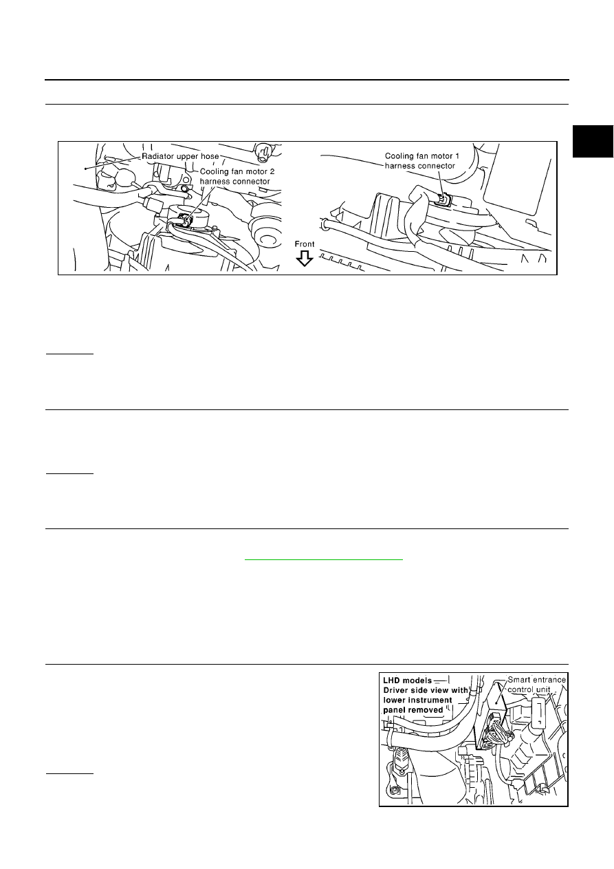
Disconnect cooling fan motor-2 harness connector.
3.
Check harness continuity between cooling fan relay-3 terminal 5 and cooling fan motor-2 terminal 1.
Refer to Wiring Diagram.
4.
Also check harness for short to ground and short to power.
OK or NG
OK
>> GO TO 4.
NG
>> Repair open circuit or short to ground short to power in harness or connectors.
4.
CHECK COOLING FAN MOTOR CONTROL CIRCUIT FOR SHORT TO GROUND
Check harness continuity between cooling fan relay-3 terminal 5 or cooling fan motor-2 terminal 1 and ground.
Refer to Wiring Diagram.
OK or NG
OK
>> GO TO 6.
NG
>> GO TO 5.
5.
DETECT MALFUNCTIONING PART
Check the following.
●
Cooling fan relays-2 and -4 (Refer to
EC-477, "Component Inspection"
)
●
Harness for short to ground between cooling fan relay-2 and cooling fan motor-2
●
Harness for short to ground between cooling fan relay-3 and cooling fan motor-2
●
Harness for short to ground between cooling fan relay-4 and cooling fan motor-2
>> Repair or replace.
6.
CHECK COOLING FAN OUTPUT SIGNAL CIRCUIT FOR OPEN AND SHORT
1.
Disconnect smart entrance control unit harness connector.
2.
Check harness continuity between cooling fan relay-3 terminal 1
and smart entrance control unit terminal 32.
Refer to Wiring Diagram.
3.
Also check harness for short to ground and short to power.
OK or NG
OK
>> GO TO 8.
NG
>> GO TO 7.
Continuity should exist.
MBIB0087E
Continuity should not exist.
Continuity should exist.
MBIB0173E
EC-476
[YD (WITHOUT EURO-OBD)]
DTC P0217 ENGINE OVER TEMPERATURE
7.
DETECT MALFUNCTIONING PART
Check the following.
●
Harness connectors E123, M17 (LHD models)
●
Harness connectors E110, M94 (RHD models)
●
Harness for open or short between cooling fan relay-3 and smart entrance control unit
>> Repair open circuit or short to ground or short to power in harness or connectors.
8.
CHECK COOLING FAN RELAY-3
Refer to
EC-477, "Component Inspection"
.
OK or NG
OK
>> GO TO 9.
NG
>> Replace cooling fan relay.
9.
CHECK SMART ENTRANCE CONTROL UNIT
Refer to
.
OK or NG
OK
>> GO TO 10.
NG
>> Replace smart entrance control unit.
10.
CHECK INTERMITTENT INCIDENT
Perform
EC-408, "TROUBLE DIAGNOSIS FOR INTERMITTENT INCIDENT"
.
>> INSPECTION END
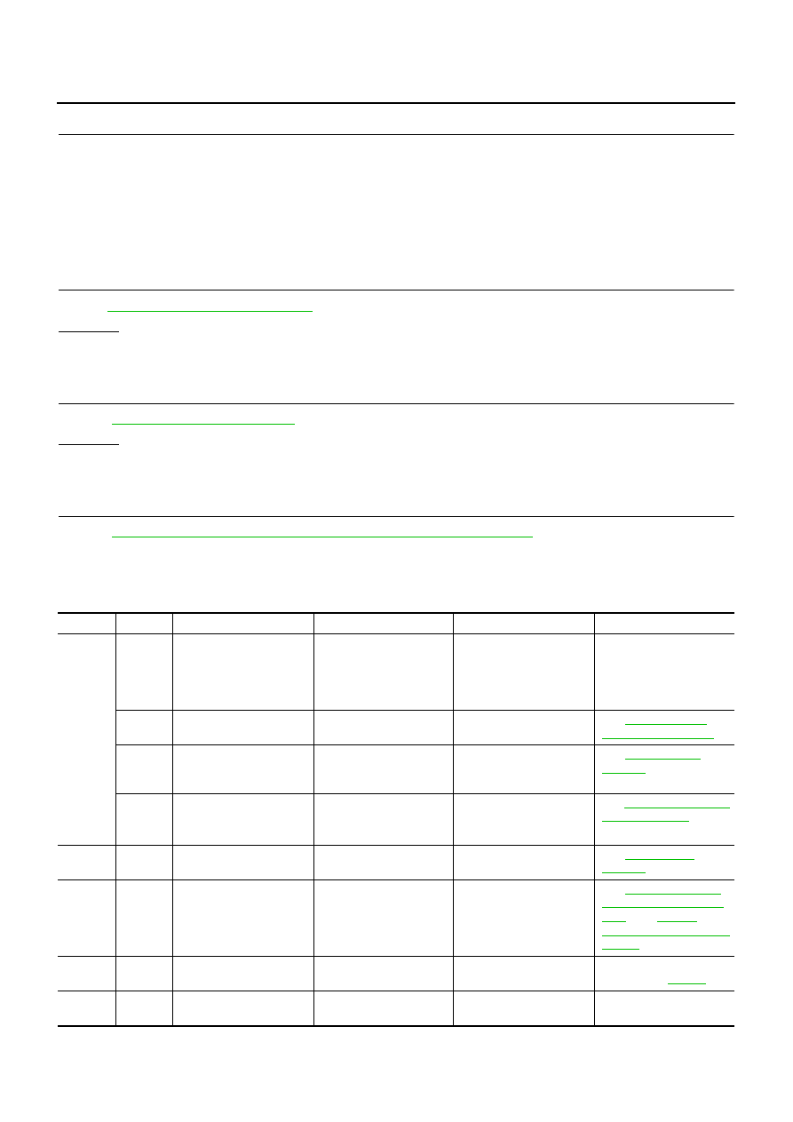
Main 12 Causes of Overheating
EBS01567
Engine
Step
Inspection item
Equipment
Standard
Reference page
OFF
1
●
Blocked radiator
●
Blocked condenser
●
Blocked radiator grille
●
Blocked bumper
●
Visual
No blocking
—
2
●
Coolant mixture
●
Coolant tester
50 - 50% coolant mixture
See
.
3
●
Coolant level
●
Visual
Coolant up to MAX level
in reservoir tank and radi-
ator filler neck
See
.
4
●
Radiator cap
●
Pressure tester
59 - 98 kPa
(0.59 - 0.98 bar, 0.6 - 1.0
kg/cm
2
, 9 - 14 psi) (Limit)
See
.
ON*
2
5
●
Coolant leaks
●
Visual
No leaks
See
.
ON*
2
6
●
Thermostat
●
Touch the upper and
lower radiator hoses
Both hoses should be hot
See
, and
.
ON*
1
7
●
Cooling fan
●
CONSULT-II
Operating
See trouble diagnosis for
DTC P0217 (
).
OFF
8
●
Combustion gas leak
●
Color checker chemical
tester 4 Gas analyzer
Negative
—
Нет комментариевНе стесняйтесь поделиться с нами вашим ценным мнением.
Текст