Nissan Primera P12. Manual — part 323
DTC P0217 ENGINE OVER TEMPERATURE
EC-477
[YD (WITHOUT EURO-OBD)]
C
D
E
F
G
H
I
J
K
L
M
A
EC
*1: Turn the ignition switch ON.
*2: Engine running at 3,000 rpm for 10 minutes.
*3: Drive at 90 km/h (55 MPH) for 30 minutes and then let idle for 10 minutes.
*4: After 60 minutes of cool down time.
For more information, refer to
CO-5, "OVERHEATING CAUSE ANALYSIS"
.
Component Inspection
EBS01568
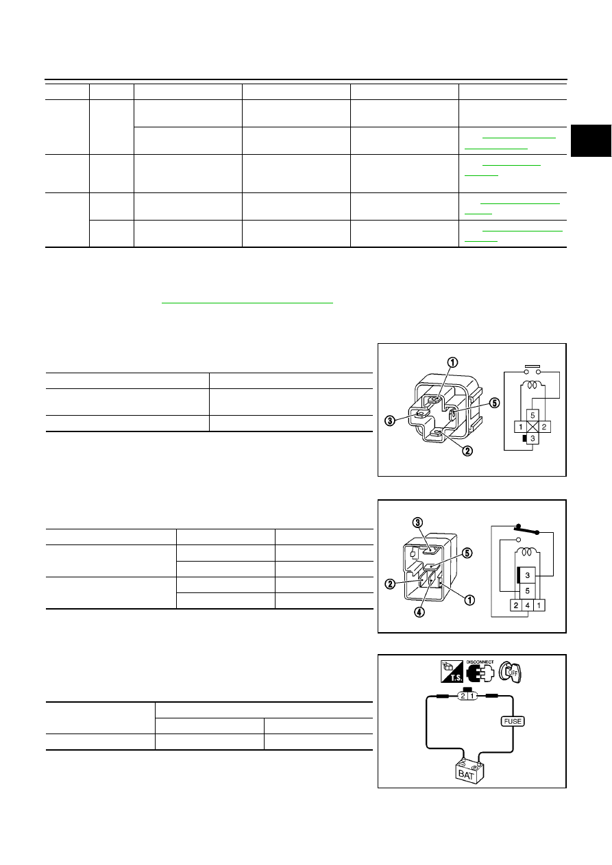
COOLING FAN RELAYS-1 AND -3
Check continuity between terminals 3 and 5 under the following con-
ditions.
COOLING FAN RELAYS-2 AND -4
Check continuity between terminals 3 and 4, 3 and 5 under the fol-
lowing conditions.
COOLING FAN MOTORS-1 AND -2
1.
Disconnect cooling fan motor harness connectors.
2.
Supply cooling fan motor terminals with battery voltage and
check operation.
ON*
3
9
●
Coolant temperature
gauge
●
Visual
Gauge less than 3/4
when driving
—
●
Coolant overflow to
reservoir tank
●
Visual
No overflow during driving
and idling
See
.
OFF*
4
10
●
Coolant return from
reservoir tank to radia-
tor
●
Visual
Should be initial level in
reservoir tank
See
.
OFF
11
●
Cylinder head
●
Straight gauge feeler
gauge
0.1 mm (0.004 in) Maxi-
mum distortion (warping)
See
.
12
●
Cylinder block and pis-
tons
●
Visual
No scuffing on cylinder
walls or piston
See
.
Engine
Step
Inspection item
Equipment
Standard
Reference page
Conditions
Continuity
12V direct current supply between ter-
minals 1 and 2
Yes
No current supply
No
MBIB1100E
Conditions
Terminals
Continuity
12V direct current supply
between terminals 1 and 2
3 and 4
No
3 and 5
Yes
No current supply
3 and 4
Yes
3 and 5
No
MBIB0056E
Terminals
(+)
(-)
Cooling fan motor
1
2
SEF721Q
EC-478
[YD (WITHOUT EURO-OBD)]
DTC P0222, P0223 APP SENSOR
DTC P0222, P0223 APP SENSOR
PFP:18002
Description
EBS01569
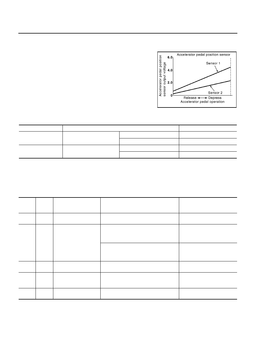
The accelerator pedal position sensor is installed on the upper end
of the accelerator pedal assembly. The sensors detect the accelera-
tor pedal position and sends a signal to the ECM. The ECM uses the
signal to determine the amount of fuel to be injected.
CONSULT-II Reference Value in Data Monitor Mode
EBS0156A
Specification data are reference values.
*: This signal is converted by ECM internally. Thus, it differs from ECM terminal voltage.
ECM Terminals and Reference Value
EBS0156B
Specification data are reference values and are measured between each terminal and ground.
CAUTION:
Do not use ECM ground terminals when measuring input/output voltage. Doing so may result in dam-
age to the ECM's transistor. Use a ground other than ECM terminals, such as the ground.
PBIB1741E
MONITOR ITEM
CONDITION
SPECIFICATION
ACCEL POS SEN*
●
Ignition switch: ON
(Engine stopped)
Accelerator pedal: fully released
0.2 - 0.7V
Accelerator pedal: fully depressed
3.9 - 4.9V
ACCEL SEN 2*
●
Ignition switch: ON
(Engine stopped)
Accelerator pedal: fully released
0.1 - 0.4V
Accelerator pedal: fully depressed
1.9 - 2.4V
TERMI-
NAL
NO.
WIRE
COLOR
ITEM
CONDITION
DATA
(DC Voltage)
82
L/R
Accelerator pedal position
sensor 1 power supply
[Ignition switch ON]
Approximately 5.3V
83
L/W
Accelerator pedal position
sensor 1
[Ignition switch ON]
●
Engine stopped
●
Accelerator pedal fully released
0.5 - 1.0V
[Ignition switch ON]
●
Engine stopped
●
Accelerator pedal fully depressed
4.2 - 5.2V
84
L
Accelerator pedal position
sensor 1 ground
[Ignition switch ON]
Approximately 0.3V
85
—
Sensor ground
(Accelerator pedal posi-
tion sensor shield circuit)
[Ignition switch ON]
Approximately 0.3V
90
R
Accelerator pedal position
sensor 2 power supply
[Ignition switch ON]
Approximately 5.3V
DTC P0222, P0223 APP SENSOR
EC-479
[YD (WITHOUT EURO-OBD)]
C
D
E
F
G
H
I
J
K
L
M
A
EC
On Board Diagnosis Logic
EBS0156C
The MI will not light up for these self-diagnoses.
DTC Confirmation Procedure
EBS0156D
NOTE:
If DTC Confirmation Procedure has been previously conducted, always turn ignition switch OFF and wait at
least 10 seconds before conducting the next test.
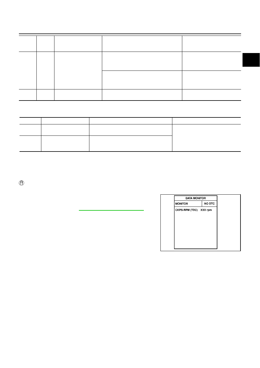
WITH CONSULT-II
1.
Turn ignition switch ON.
2.
Select “DATA MONITOR” mode with CONSULT-II.
3.
Wait at least 5 seconds.
4.
If DTC is detected, go to
EC-481, "Diagnostic Procedure"
.
91
W
Accelerator pedal position
sensor 2
[Ignition switch ON]
●
Engine stopped
●
Accelerator pedal fully released
0.4 - 0.7V
[Ignition switch ON]
●
Engine stopped
●
Accelerator pedal fully depressed
2.2 - 2.7V
92
B
Accelerator pedal position
sensor 2 ground
[Ignition switch ON]
Approximately 0.3V
TERMI-
NAL
NO.
WIRE
COLOR
ITEM
CONDITION
DATA
(DC Voltage)
DTC No.
Trouble diagnosis name
DTC detecting condition
Possible cause
P0222
Accelerator pedal position
sensor 2 circuit low input
An excessively low voltage from the APP sensor
2 is sent to ECM.
●
Harness or connectors
(The APP sensor 2 circuit is open or
shorted.)
●
Accelerator pedal position sensor
(Accelerator pedal position sensor 2)
P0223
Accelerator pedal position
sensor 2 circuit high input
An excessively high voltage from the APP sen-
sor 2 is sent to ECM.
SEF817Y
EC-480
[YD (WITHOUT EURO-OBD)]
DTC P0222, P0223 APP SENSOR
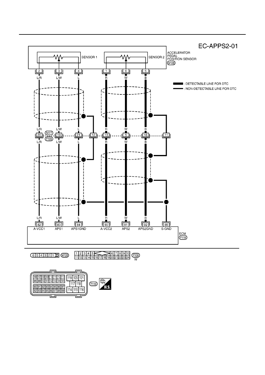
Wiring Diagram
EBS0156E
MBWA0432E
Нет комментариевНе стесняйтесь поделиться с нами вашим ценным мнением.
Текст