Nissan March K13. Manual — part 336

FSU-8
< PERIODIC MAINTENANCE >
WHEEL ALIGNMENT
WARNING:
• Always perform the following procedure on a flat surface.
• Check that no person is in front of vehicle before pushing it.
1.
Bounce front of vehicle up and down to stabilize the vehicle height (posture).
2.
Push vehicle straight ahead about 5 m (16 ft).
3.
Put matching mark (A) on base line of the tread (rear side) of
both tires at the same height of hub center. These are measur-
ing points.
4.
Measure distance (A) (rear side).
5.
Push vehicle slowly ahead to rotate wheels 180 degrees (1/2
turn).
NOTE:
If the wheels rotates more than 180 degrees (1/2 turn), start this
procedure again from the beginning. Do not push the vehicle
backward.
6.
Measure distance (B) (front side).
• If toe-in exceeds the standard value, adjust toe-in by varying the length of between steering outer socket
and inner socket.
JPEIA0014ZZ
: Vehicle front
Total toe-in = A – B
Total toe-in
: Refer to
JPEIA0015ZZ
FRONT COIL SPRING AND STRUT
FSU-9
< REMOVAL AND INSTALLATION >
C
D
F
G
H
I
J
K
L
M
A
B
FSU
N
O
P
REMOVAL AND INSTALLATION
FRONT COIL SPRING AND STRUT
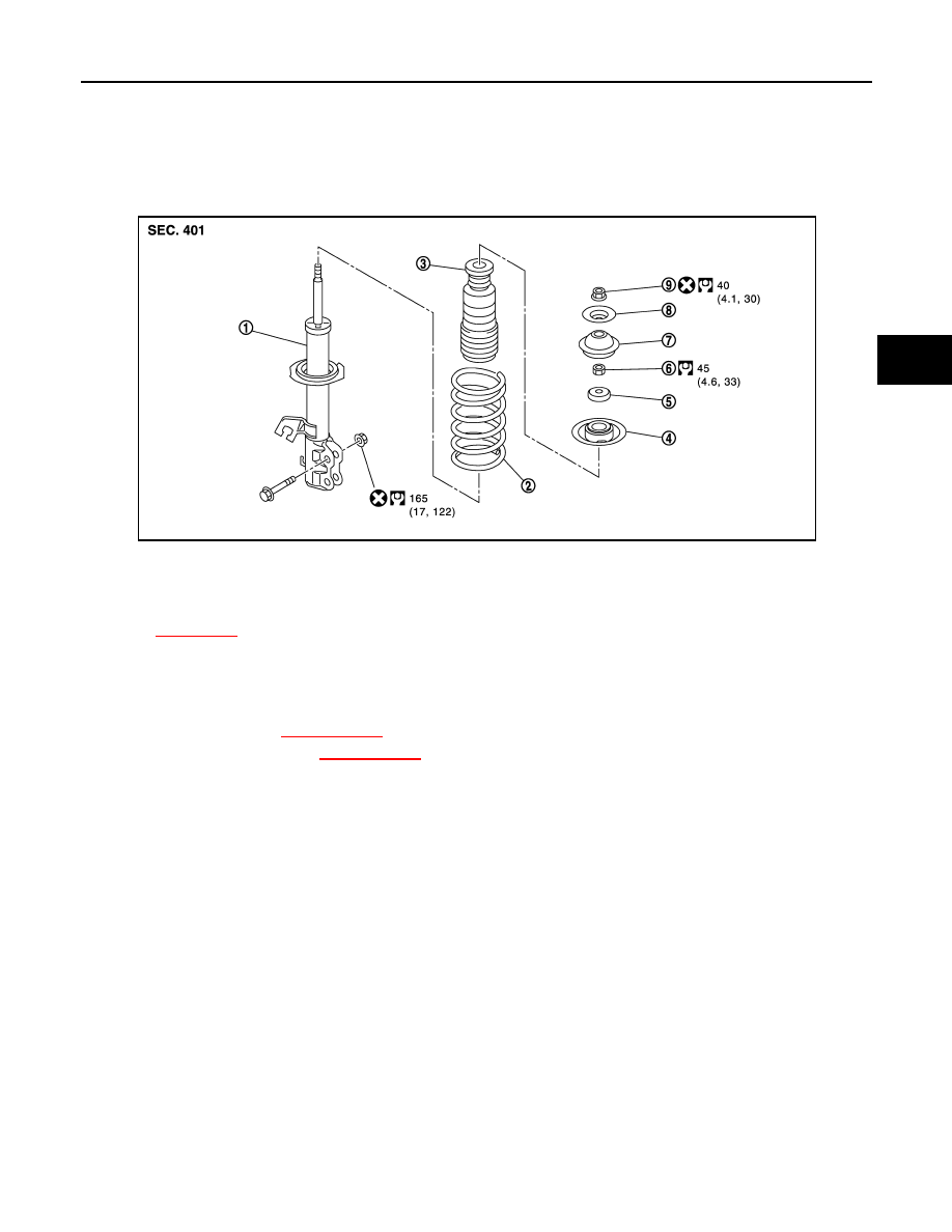
Exploded View
INFOID:0000000006046088
Removal and Installation
INFOID:0000000006046089
REMOVAL
1.
Remove tires. Refer to
XX-XX, "*****"
.
2.
Remove lock plate. Refer to
XX-XX, "*****"
.
3.
Remove strut mounting bolts and nuts from steering knuckle.
4.
Remove stopper insulator lock nut and stopper insulator.
5.
Remove strut assembly.
INSTALLATION
Note the following, and install in the reverse order of removal.
• Perform final tightening of bolts and nuts, under unladen conditions with tires on level ground.
• Never reuse strut mounting nut and stopper insulator lock nut.
Disassembly and Assembly
INFOID:0000000006046090
DISASSEMBLY
CAUTION:
Never damage strut assembly piston rod when removing components from strut assembly.
1.
Remove strut mounting insulator.
2.
Install strut attachment (SST: ST35652000) to strut assembly and secure it in a vise.
CAUTION:
When installing the strut attachment to strut assembly, wrap a shop cloth around strut to protect
from damage.
3.
Using a spring compressor (commercial service tool), compress coil spring between spring upper seat
and lower seat (strut assembly) until coil spring with a spring compressor is free.
CAUTION:
1.
Strut
2.
Coil spring
3.
Bound bumper
4.
Spring upper seat
5.
Strut mounting bearing
6.
Piston rod lock nut
7.
Strut mounting insulator
8.
Stopper insulator
9.
Stopper insulator lock nut
Refer to
XX-XX, "*****"
for symbols in the figure.
JPEIA0226GB
FSU-10
< REMOVAL AND INSTALLATION >
FRONT COIL SPRING AND STRUT
Be sure a spring compressor is securely attached to coil spring. Compress coil spring.
4.
Check coil spring with a spring compressor between spring upper seat and lower seat (strut assembly) is
free. And then remove piston rod lock nut while securing the piston rod tip so that piston rod does not turn.
5.
Remove strut mounting bearing, spring upper seat, and bound bumper as a set.
6.
Remove bound bumper from spring upper seat.
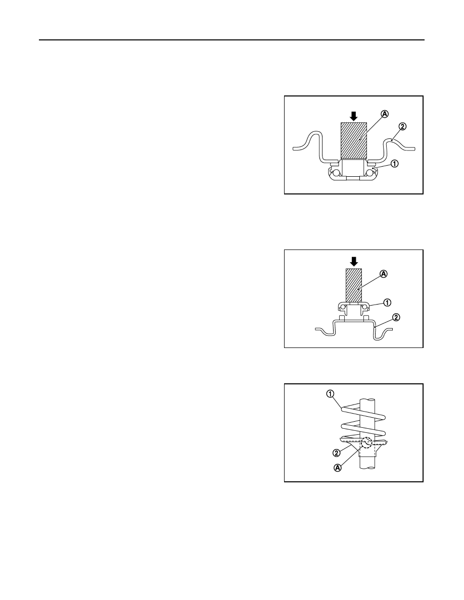
7.
Remove strut mounting bearing (1) from spring upper seat (2),
using a drift (A) (SST: KV10106700).
8.
After removing coil spring with a spring compressor, then gradu-
ally release a spring compressor.
CAUTION:
Loosen while making sure coil spring attachment position
does not move.
9.
Remove the strut attachment (SST: ST35652000) from strut.
ASSEMBLY
1.
Install strut attachment (SST: ST35652000) to strut and secure it in a vise.
CAUTION:
When installing the strut attachment to strut assembly, wrap a shop cloth around strut to protect
from damage.
2.
Install strut mounting bearing (1) to spring upper seat (2), using
a drift (A) (SST: KV10106700).
CAUTION:
Never press to aluminum shield.
3.
Install bound bumper to spring upper seat.
4.
Compress coil spring using a spring compressor (commercial service tool), and install it onto strut assem-
bly.
CAUTION:
• Face tube side of coil spring (1) downward. Align the
lower end (A) to lower seat (strut assembly) (2).
• Be sure a compressor is securely attached to coil spring.
Compress coil spring.
5.
Install strut mounting bearing, spring upper seat, and bound
bumper as a set.
6.
Secure piston rod tip so that piston rod does not turn, then
tighten piston rod lock nut with specified torque.
7.
Gradually release a spring compressor, and remove coil spring.
CAUTION:
Loosen while making sure coil spring attachment position
does not move.
8.
Remove the strut attachment from strut assembly.
9.
Install strut mounting insulator.
Inspection
INFOID:0000000006046091
INSPECTION AFTER DISASSEMBLY
Check the following items, and replace the parts if necessary.
Strut
JPEIA0228ZZ
JPEIA0229ZZ
JPEIA0095ZZ

FRONT COIL SPRING AND STRUT
FSU-11
< REMOVAL AND INSTALLATION >
C
D
F
G
H
I
J
K
L
M
A
B
FSU
N
O
P
• Strut for deformation, cracks or damage
• Piston rod for damage, uneven wear or distortion
• Oil leakage
Strut Mounting Insulator and bound bumper Inspection
Check strut mounting insulator and bound bumper for cracks, wear or damage.
Coil Spring
Check coil spring for cracks, wear or damage.
INSPECTION AFTER INSTALLATION
1.
Check wheel alignment. Refer to
2.
Adjust neutral position of steering angle sensor. Refer to
XX-XX, "*****"
.
Disposal
INFOID:0000000006046092
1.
Set strut assembly horizontally to the ground with the piston rod fully extracted.
2.
Drill 2 – 3 mm (0.08 – 0.12 in) hole at the position (
) from top
as shown in the figure to release gas gradually.
CAUTION:
• Wear eye protection (safety glass).
• Wear gloves.
• Be careful with metal chips or oil blown out by the com-
pressed gas.
NOTE:
• Drill vertically in this direction (
).
• Directly to the outer tube avoiding brackets.
• The gas is clear, colorless, odorless, and harmless.
3.
Position the drilled hole downward and drain oil by moving the piston rod several times.
CAUTION:
Dispose of drained oil according to the law and local regulations.
A
: 20 – 30 mm (0.79 – 1.18 in)
JPEIA0160ZZ
Нет комментариевНе стесняйтесь поделиться с нами вашим ценным мнением.
Текст