Nissan March K13. Manual — part 335
FSU-4
< PREPARATION >
PREPARATION
PREPARATION
PREPARATION
Special Service Tool
INFOID:0000000006046084
Commercial Service Tool
INFOID:0000000006046085
Tool number
Tool name
Description
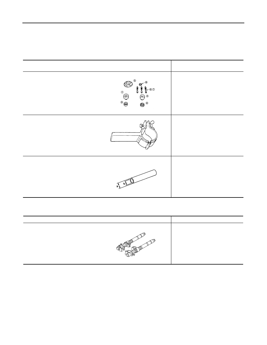
KV991040S1
1. KV99104020 Adapter A
2. KV99104030 Adapter B
3. KV99104040 Adapter C
4. KV99104050 Adapter D
5. KV99104060 Plate
6. KV99104070 Guide bolt
7. KV99104080 Spring
8. KV99104090 Center plate
Measuring wheel alignment
ST35652000
Strut attachment
Disassembling and assembling strut
KV10106700
Drift
a: 25 mm (0.98 in) dia.
a: 18.5 mm (0.728 in) dia.
Disassembling and assembling strut
mounting bearing.
ZZA1167D
ZZA0807D
ZZA0534D
Tool name
Description
Spring compressor
Removing and installing coil spring
S-NT717
NOISE, VIBRATION AND HARSHNESS (NVH) TROUBLESHOOTING
FSU-5
< SYMPTOM DIAGNOSIS >
C
D
F
G
H
I
J
K
L
M
A
B
FSU
N
O
P
SYMPTOM DIAGNOSIS
NOISE, VIBRATION AND HARSHNESS (NVH) TROUBLESHOOTING
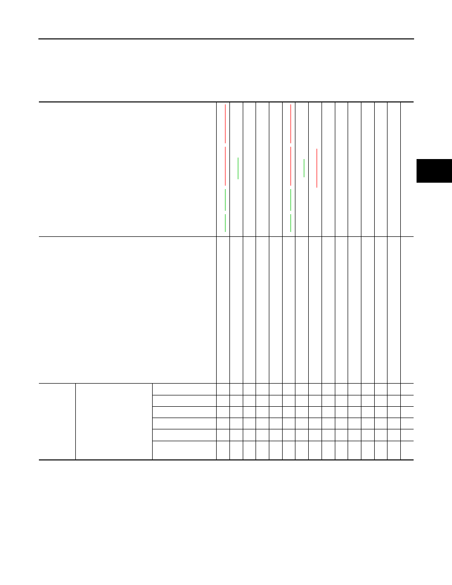
NVH Troubleshooting Chart
INFOID:0000000006046080
Use chart below to find the cause of the symptom. If necessary, repair or replace these parts.
×
: Applicable
Reference page
,
,
XX-XX, "*****"
,
XX-X
X
, "*****"
—
—
—
,
,
XX-XX, "*****"
,
XX-X
X
, "*****"
XX-XX
, "*****"
NVH in DLN
section
NVH
in F
AX and
FS
U
sections
NVH in
WT section
NVH in
WT section
NVH in F
A
X section
NVH in BR
section
NVH in ST
section
Possible cause and SUSPECTED PARTS
Im
prop
er ins
ta
lla
ti
on,
lo
os
en
es
s
Sh
oc
k ab
so
rbe
r de
fo
rma
tio
n,
da
ma
ge
or de
fl
e
c
ti
on
Bu
sh
in
g o
r
m
o
u
n
ti
ng
de
te
ri
ora
ti
o
n
Part
s interference
S
p
ring
fa
tig
u
e
Su
sp
en
si
on
lo
os
en
es
s
Inc
o
rre
c
t whe
e
l al
ig
nm
en
t
S
ta
b
iliz
er ba
r
fa
tig
u
e
DIFFERE
N
T
IAL
FRONT AXLE AND F
R
ONT
SUSPENSI
ON
TIRE
RO
A
D
WHEE
L
DRIVE SHAF
T
BRAKE
STEERI
N
G
Symptom
FRONT SUSPENSION
Noise
×
×
×
×
×
×
×
×
×
×
×
×
×
Shake
×
×
×
×
×
×
×
×
×
×
×
Vibration
×
×
×
×
×
×
×
×
×
Shimmy
×
×
×
×
×
×
×
×
×
×
Judder
×
×
×
×
×
×
×
×
Poor quality ride or
handling
×
×
×
×
×
×
×
×
×
×
FSU-6
< PERIODIC MAINTENANCE >
FRONT SUSPENSION ASSEMBLY
PERIODIC MAINTENANCE
FRONT SUSPENSION ASSEMBLY
Inspection
INFOID:0000000006046086
COMPONENT PART
Check the mounting conditions (looseness, backlash) of each component and component conditions (wear,
damage) are normal.
BALL JOINT AXIAL END PLAY
1.
Set front wheels in a straight-ahead position.
2.
Measure axial end play by prying it up/down with iron bar or equivalent between transverse link and steer-
ing knuckle.
CAUTION:
• Never depress brake pedal when measuring.
• Never perform with tires on level ground.
• Be careful not to damage ball joint boot. Never damage the installation position by applying
excessive force.
STRUT ASSEMBLY
Check for oil leakage, damage, and replace if necessary.
Axial end play
: Refer to
WHEEL ALIGNMENT
FSU-7
< PERIODIC MAINTENANCE >
C
D
F
G
H
I
J
K
L
M
A
B
FSU
N
O
P
WHEEL ALIGNMENT
Inspection
INFOID:0000000006046087
DESCRIPTION
CAUTION:
• Camber, caster, kingpin inclination angles cannot be adjusted.
• If camber, caster, or kingpin inclination angle is outside the standard, check front suspension parts
for wear and damage. Replace suspect parts if a malfunction is detected.
• Kingpin inclination angle is reference value, no inspection is required.
Measure wheel alignment under unladen conditions.
NOTE:
“Unladen conditions” means that fuel, engine coolant, and lubricant are full. Spare tire, jack, hand tools and
mats are in designated positions.
PRELIMINARY CHECK
Check the following:
• Tires for improper air pressure and wear.
• Road wheels for runout. Refer to
XX-XX, "*****"
.
• Wheel bearing axial end play. Refer to
XX-XX, "*****"
(HR16DE) or
XX-XX, "*****"
(K9K).
• Transverse link ball joint axial end play. Refer to
.
• Strut operation.
• Each mounting part of axle and suspension for looseness and deformation.
• Each of suspension member, strut and transverse link for cracks, deformation and other damage.
• Vehicle height (posture).
CAMBER, CASTER, AND KINGPIN INCLINATION ANGLES
• Camber, caster, kingpin inclination angles cannot be adjusted.
• Before inspection, mount front wheels onto turning radius gauge. Mount rear wheels onto a stand at the
same height so that vehicle remains horizontal.
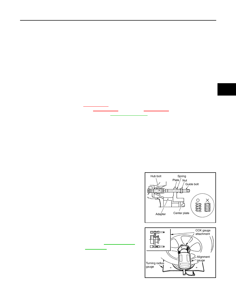
Using a CCK Gauge
Install the CCK gauge attachment (SST: KV991040S1) with the following procedure on wheel, then measure
wheel alignment.
1.
Remove three wheel to nuts, and install the guide bolts to hub
bolt.
2.
Screw the adapter into the plate until it contacts the plate tightly.
3.
Screw the center plate into the plate.
4.
Insert the plate assembly on the guide bolt. Put the spring in,
and then evenly screw the three guide bolt nuts. When fastening
the guide nuts, do not completely compress the spring.
5.
Place the dent of alignment gauge onto the projection of the
center plate and tightly contact them to measure.
CAUTION:
• If camber, caster, or kingpin inclination angle exceeds the
standard value, check front suspension parts for wear and
damage. Replace suspect parts if a malfunction is
detected.
• Kingpin inclination angle is reference value, no inspection
is required.
TOE-IN
Measure toe-in by the following procedure.
SEIA0240E
Camber, caster, kingpin
inclination angles
: Refer to
SEIA0241E
Нет комментариевНе стесняйтесь поделиться с нами вашим ценным мнением.
Текст