Nissan March K13. Manual — part 151
ECM
EC-65
< ECU DIAGNOSIS INFORMATION >
[HR12DE (TYPE 1)]
C
D
E
F
G
H
I
J
K
L
M
A
EC
N
P
O
ECU DIAGNOSIS INFORMATION
ECM
Reference Value
INFOID:0000000005995470
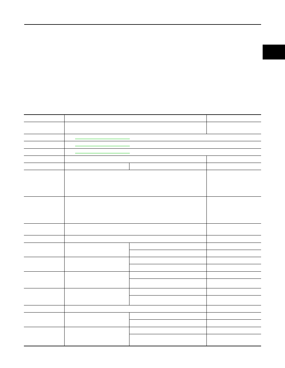
VALUES ON THE DIAGNOSIS TOOL
Remarks:
• Specification data are reference values.
• Specification data are output/input values which are detected or supplied by the ECM at the connector.
*1 Specification data may not be directly related to their components signals/values/operations.
I.e. Adjust ignition timing with a timing light before monitoring IGN TIMING, because the monitor may show the
specification data in spite of the ignition timing not being adjusted to the specification data. this IGN TIMING
monitors the data calculated by the ECM according to the signals input from the camshaft position sensor and
other ignition timing related sensors.
Monitor Item
Condition
Values/Status
ENG SPEED
• Run engine and compare CONSULT-III value with the tachometer indication.
Almost the same speed as
the tachometer indication.
MAS A/F SE-B1
See
.
B/FUEL SCHDL
See
.
A/F ALPHA-B1
See
.
COOLAN TEMP/S
• Engine: After warming up
More than 70
°
C (158
°
F)
A/F SEN1 (B1)
• Engine: After warming up
Maintaining engine speed at 2,000 rpm
Fluctuates around 2.2 V
HO2S2 (B1)
• Revving engine from idle up to 3,000 rpm quickly after the following conditions
are met.
- Engine: After warming up
- After keeping engine speed between 3,500 and 4,000 rpm for 1 minute and at
idle for 1 minute under no load
0 - 0.3 V
←→
Approx. 0.6 -
1.0 V
HO2S2 MNTR (B1)
• Revving engine from idle up to 3,000 rpm quickly after the following conditions
are met.
- Engine: After warming up
- After keeping engine speed between 3,500 and 4,000 rpm for 1 minute and at
idle for 1 minute under no load
LEAN
←→
RICH
VHCL SPEED SE
• Turn drive wheels and compare CONSULT-III value with the speedometer in-
dication.
Almost the same speed as
speedometer indication
BATTERY VOLT
• Ignition switch: ON (Engine stopped)
11 - 14 V
ACCEL SEN 1
• Ignition switch: ON
(Engine stopped)
Accelerator pedal: Fully released
0.6 - 0.9 V
Accelerator pedal: Fully depressed
4.0 - 4.8 V
ACCEL SEN 2
• Ignition switch: ON
(Engine stopped)
Accelerator pedal: Fully released
0.6 - 0.9 V
Accelerator pedal: Fully depressed
3.9 - 4.8 V
TP SEN 1-B1
• Ignition switch: ON
(Engine stopped)
• Shift lever: 1st
Accelerator pedal: Fully released
More than 0.36 V
Accelerator pedal: Fully depressed
Less than 4.75 V
TP SEN 2-B1
• Ignition switch: ON
(Engine stopped)
• Shift lever:1st
Accelerator pedal: Fully released
More than 0.36 V
Accelerator pedal: Fully depressed
Less than 4.75 V
START SIGNAL
• Ignition switch: ON
→
START
→
ON
Off
→
On
→
Off
CLSD THL POS
• Ignition switch: ON
(Engine stopped)
Accelerator pedal: Fully released
On
Accelerator pedal: Slightly depressed
Off
AIR COND SIG
• Engine: After warming up, idle
the engine
Air conditioner switch: OFF
Off
Air conditioner switch: ON
(Compressor operates.)
On

EC-66
< ECU DIAGNOSIS INFORMATION >
[HR12DE (TYPE 1)]
ECM
PW/ST SIGNAL
• Engine: After warming up, idle
the engine
Steering wheel: Not being turned
Off
Steering wheel: Being turned
On
LOAD SIGNAL
• Ignition switch: ON
Rear window defogger switch: ON
and/or Lighting switch: 2nd position
On
Rear window defogger switch and lighting
switch: OFF
Off
IGNITION SW
• Ignition switch: ON
→
OFF
→
ON
On
→
Off
→
On
HEATER FAN SW
• Engine: After warming up, idle
the engine
Heater fan switch: ON
On
Heater fan switch: OFF
Off
BRAKE SW
• Ignition switch: ON
Brake pedal: Fully released
Off
Brake pedal: Slightly depressed
On
INJ PULSE-B1
• Engine: After warming up
• Shift lever: Neutral
• Air conditioner switch: OFF
• No load
Idle
2.0 - 3.0 msec
2,000 rpm
1.9 - 2.9 msec
IGN TIMING
• Engine: After warming up
• Shift lever: Neutral
• Air conditioner switch: OFF
• No load
Idle
12
°
BTDC
2,000 rpm
25
°
- 45
°
BTDC
CAL/LD VALUE
• Engine: After warming up
• Selector lever position: Neutral
• Air conditioner switch: OFF
• No load
Idle
10% - 35%
2,500 rpm
10% - 35%
MASS AIRFLOW
• Engine: After warming up
• Selector lever position: Neutral
• Air conditioner switch: OFF
• No load
Idle
1.0 - 4.0 g·m/s
2,500 rpm
2.0 - 10.0 g·m/s
PURG VOL C/V
• Engine: After warming up
• Shift lever: Neutral
• Air conditioner switch: OFF
• No load
Idle
(Accelerator pedal is not depressed even
slightly, after engine starting)
0%
2,000 rpm
0% - 50%
EGR VOL CON/V
• Engine: After warming up
• Shift lever: P or N
• Air conditioner switch: OFF
• No load
Idle
0 - 1 step
Revving engine from idle up to 3,000 rpm
quickly
0 - 33 step
INT/V TIM(B1)
• Engine: After warming up
• Shift lever: Neutral
• Air conditioner switch: OFF
• No load
Idle
−
5
°
- 5
°
CA
When revving engine up to 2,000rpm
Quickly
Approx. 0
°
- 40
°
CA
INT/V SOL(B1)
• Engine: After warming up
• Shift lever: Neutral
• Air conditioner switch: OFF
• No load
Idle
0% - 2%
When revving engine up to 2,000rpm
Quickly
Approx. 0% - 90%
AIR COND RLY
• Engine: After warming up, idle
the engine
Air conditioner switch: OFF
Off
Air conditioner switch: ON
(Compressor operates)
On
FUEL PUMP RLY
• For 1 seconds after turning ignition switch: ON
• Engine running or cranking
On
• Except above
Off
THRTL RELAY
• Ignition switch: ON
On
Monitor Item
Condition
Values/Status

ECM
EC-67
< ECU DIAGNOSIS INFORMATION >
[HR12DE (TYPE 1)]
C
D
E
F
G
H
I
J
K
L
M
A
EC
N
P
O
*1: Accelerator pedal position sensor 2 signal and throttle position sensor 2 signal are converted by ECM inter-
nally. Thus, they differ from ECM terminals voltage signal.
*2: Although the state is indicated as "LOW," the cooling fan operates at high speeds.
COOLING FAN
• Engine: After warning up, idle the
engine
• Air conditioner switch: OFF
Engine coolant temperature is 98
°
C
(208
°
F) or less
Off
Engine coolant temperature is between
98
°
C (208
°
F) and 99
°
C (210
°
F)
LOW
*2
Engine coolant temperature is 100
°
C
(212
°
F) or more
HIGH
HO2S2 HTR (B1)
• Engine speed: Below 3,900 rpm after the following conditions are met.
- Engine: After warming up
- Keeping the engine speed between 3,500 and 4,000 rpm for 1 minute and at
idle for 1 minute under no load
On
• Engine speed: Above 3,900 rpm
OFF
ALT DUTY SIG
• Power generation voltage variable control: Operating
ON
• Power generation voltage variable control: Not operating
OFF
VEHICLE SPEED
• Turn drive wheels and compare CONSULT-III value with the speedometer in-
dication.
Almost the same speed as
speedometer indication
IDL A/V LEARN
• Engine: running
Idle air volume learning has not been per-
formed yet.
YET
Idle air volume learning has already been
performed successfully.
CMPLT
TRVL AFTER MIL
• Ignition switch: ON
Vehicle has traveled after MIL has turned
ON.
0 - 65,535 km
(0 - 40,723 miles)
A/F S1 HTR(B1)
• Engine: After warming up, idle the engine
(More than 140 seconds after starting engine)
4 - 100%
ALT DUTY
• Engine: Idle
0 - 80%
BAT CUR SEN
• Engine speed: Idle
• Battery: Fuel charged
*3
• Selector lever: Neutral
• Air conditioner switch: OFF
• No load
Approx 2,500 - 3,500 mV
A/F ADJ-B1
• Engine: Running
-0.330 - 0.330
P/N POSI SW
• Ignition switch: ON
Selector lever: Neutral
ON
Selector lever: Except above
OFF
INT/A TEMP SE
• Ignition switch: ON
Indicates intake air tempera-
ture.
AC PRESS SEN
• Engine: Idle
• Both A/C switch and blower fan switch: ON (Compressor operates)
1.0 - 4.0 V
EGR TEMP SEN
• Engine: After warming up
Less than 4.8 V
FPCM
• Ignition switch: OFF
Off
• For 1 seconds after turning ignition switch: ON
Low
• Engine: Idle
• Engine coolant temperature: More than 10
°
C (50
°
F)
Mid
• Engine: Cranking
Hi
THRTL STK CNT B1
• Ignition switch: ON
A value corresponding to the
number of cloggings in the
throttle valve closed position
HO2 S2 DIAG2(B1)
NOTE:
The item is indicated, but not used.
—
A/F SEN1 DIAG2
(B1)
NOTE:
The item is indicated, but not used.
—
Monitor Item
Condition
Values/Status
EC-68
< ECU DIAGNOSIS INFORMATION >
[HR12DE (TYPE 1)]
ECM
*3: Before measuring the terminal voltage, confirm that the battery is fully charged. Refer to
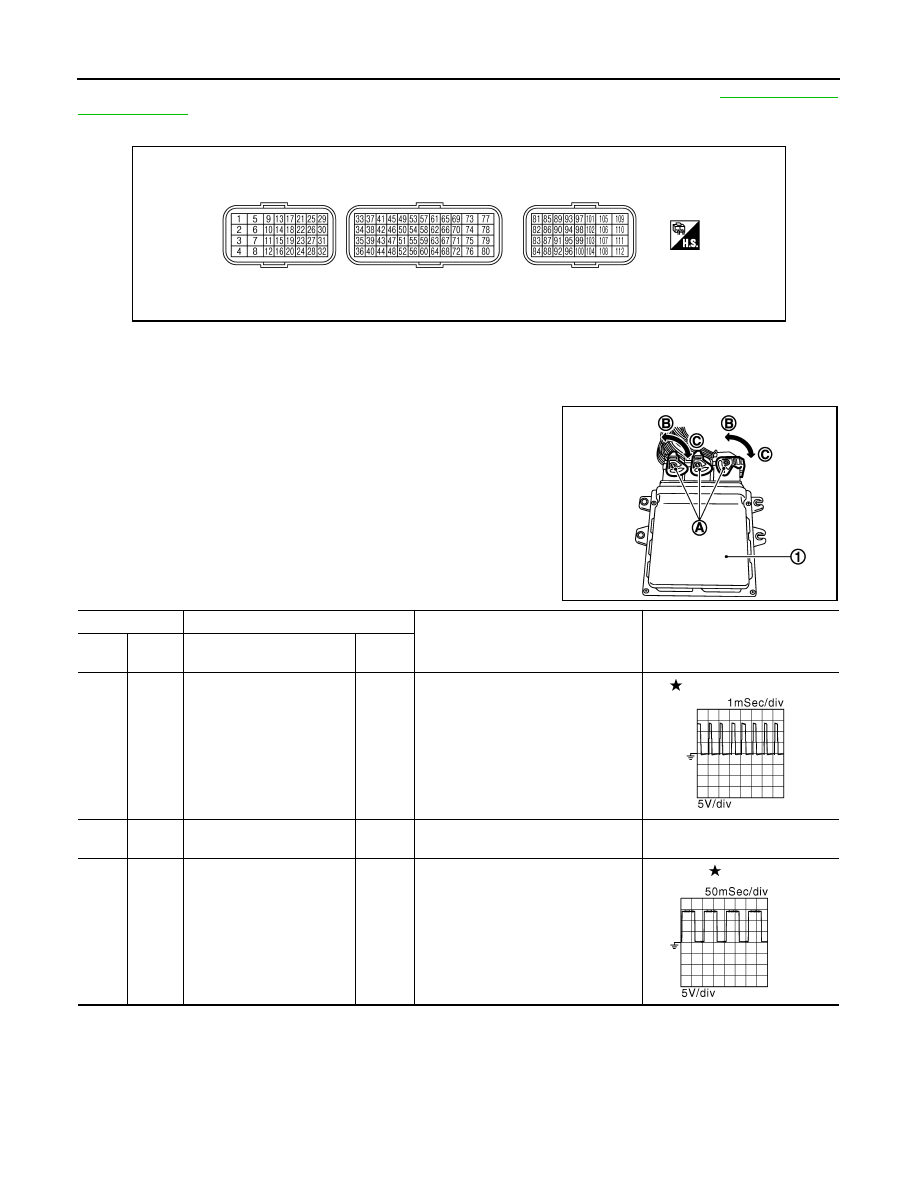
TERMINAL LAYOUT
PHYSICAL VALUES
NOTE:
• ECM is located in the engine room left side near battery.
• When disconnecting ECM harness connector (A), loosen (C) it with
levers as far as they will go as shown in the figure.
- ECM (1)
- Fasten (B)
• Connect a break-out box and harness adapter between the ECM
and ECM harness connector.
- Use extreme care not to touch 2 pins at one time.
- Data is for comparison and may not be exact.
• Specification data are reference values and are measured
between each terminals.
• Pulse signal is measured by CONSULT-III.
PBIA9221J
JMBIA0029ZZ
Terminal No.
Description
Condition
Value
(Approx.)
+
–
Signal name
Input/
Output
1
(L)
107
(B)
Throttle control motor
(Open)
Output
[Ignition switch: ON]
• Engine stopped
• Shift lever: 1st position
• Accelerator pedal: Fully depressed
2 V
2
(SB)
107
(B)
Throttle control motor power
supply
Input
[Ignition switch: ON]
BATTERY VOLTAGE
(11 - 14 V)
3
(G)
107
(B)
A/F sensor 1 heater
Output
[Engine is running]
• Warm-up condition
• Idle speed
(More than 140 seconds after start-
ing engine)
2.9 - 8.8 V
JMBIA0213GB
JMBIA0030GB
Нет комментариевНе стесняйтесь поделиться с нами вашим ценным мнением.
Текст