Nissan March K13. Manual — part 150

ON BOARD DIAGNOSTIC (OBD) SYSTEM
EC-61
< SYSTEM DESCRIPTION >
[HR12DE (TYPE 1)]
C
D
E
F
G
H
I
J
K
L
M
A
EC
N
P
O
*: Although the state is indicated as “LOW” the cooling fan operates at high speeds.
NOTE:
Any monitored item that does not match the vehicle being diagnosed is deleted from the display automatically.
ACTIVE TEST MODE
Test Item
ALT DUTY
%
• Indicates the duty ratio of the power generation
command value. The ratio is calculated by ECM
based on the battery current sensor signal.
BAT CUR SEN
mV
• The signal voltage of battery current sensor is
displayed.
A/F ADJ-B1
—
• Indicates the correction of factor stored in ECM.
The factor is calculated from the difference be-
tween the target air-fuel ratio stored in ECM and
the air-fuel ratio calculated from A/F sensor 1 sig-
nal.
P/N POSI SW
ON/OFF
• Indicates [ON/OFF] condition from the park/neu-
tral position (PNP) switch signal.
INT/A TEMP SE
°
C or
°
F
• The intake air temperature (determined by the
signal voltage of the intake air temperature sen-
sor) is indicated.
AC PRESS SEN
V
• The signal voltage from the refrigerant pressure
sensor is displayed.
EGR TEMP SEN
V
• The signal voltage of EGR temperature sensor is
displayed.
FPCM
Hi/Mid/Low/
Off
• The control condition of the fuel pump control
module (FPCM) (determined by ECM according
to the input signals) is indicated.
THRTL STK CNT B1
—
• The number of cloggings in the throttle valve
closed position is displayed.
NOTE:
This is cleared after repeating non-clogging con-
dition several times.
HO2 S2 DIAG2 (B1)
—
NOTE:
The item is indicated, but not used.
A/F SEN1 DIAG2
(B1)
—
NOTE:
The item is indicated, but not used.
Monitored item
Unit
Description
Remarks
TEST ITEM
CONDITION
JUDGMENT
CHECK ITEM (REMEDY)
ENG COOLANT
TEMP
• Engine: Return to the original
trouble condition
• Change the engine coolant tem-
perature using CONSULT-III.
If trouble symptom disappears, see
CHECK ITEM.
• Harness and connectors
• Engine coolant temperature
sensor
• Fuel injector
FUEL INJECTION
• Engine: Return to the original
trouble condition
• Change the amount of fuel injec-
tion using CONSULT-III.
If trouble symptom disappears, see
CHECK ITEM.
• Harness and connectors
• Fuel injector
• Air fuel ratio (A/F) sensor 1
PURG VOL CONT/V
• Engine: After warming up, run en-
gine at 1,500 rpm.
• Change the EVAP canister purge
volume control solenoid valve
opening percent using CON-
SULT-III.
Engine speed changes according
to the opening percent.
• Harness and connectors
• Solenoid valve

EC-62
< SYSTEM DESCRIPTION >
[HR12DE (TYPE 1)]
ON BOARD DIAGNOSTIC (OBD) SYSTEM
*: Leaving cooling fan OFF with CONSULT-III while engine is running may cause the engine to overheat.
WORK SUPPORT MODE
Work Item
*: This function is not necessary in the usual service procedure.
DTC & SRT CONFIRMATION MODE
SRT STATUS Mode
For details, refer to “How to Display SRT Code” in
EC-45, "Diagnosis Description"
FUEL PUMP RELAY
• Ignition switch: ON (Engine
stopped)
• Turn the fuel pump relay “ON”
and “OFF” using CONSULT-III
and listen to operating sound.
Fuel pump relay makes the operat-
ing sound.
• Harness and connectors
• Fuel pump relay
IGNITION TIMING
• Engine: Return to the original
trouble condition
• Timing light: Set
• Retard the ignition timing using
CONSULT-III.
If trouble symptom disappears, see
CHECK ITEM.
• Perform Idle Air Volume Learn-
ing.
ALTERNATOR
DUTY
• Engine: idle.
• Change duty ratio using CON-
SULT-III.
Battery voltage cangees.
• Harness and connectors
• IPDM E/R
• Alternator
COOLING FAN*
• Ignition switch: ON
• Turn the cooling fan “LOW”, “HI”
and “OFF” CONSULT-III.
NOTE:
The cooling fan operates at high
speeds even when “LOW” is se-
lected.
Cooling fan moves and stops.
• Harness and connectors
• IPDM E/R (Cooling fan relay)
• Cooling fan motor
V/T ASSIGN ANGLE
• Engine: Return to the original
trouble condition
• Change intake valve timing using
CONSULT-III.
If trouble symptom disappears, see
CHECK ITEM.
• Harness and connectors
• Intake valve timing control sole-
noid valve
EGR VOL
CONT/V
• Ignition switch: ON
(Engine stopped)
• Change the EGR volume control
valve opening step using CON-
SULT-III.
EGR volume control valve makes
an operating sound.
• Harness and connectors
• EGR volume control valve
POWER BALANCE
• Engine: After warming up, idle the
engine.
• A/C switch OFF
• Shift lever: Neutral
• Cut off each fuel injector signal
one at a time using CONSULT-III.
Engine runs rough or dies.
• Harness and connectors
• Compression
• Fuel injector
• Power transistor
• Spark plug
• Ignition coil
TEST ITEM
CONDITION
JUDGMENT
CHECK ITEM (REMEDY)
WORK ITEM
CONDITION
USAGE
FUEL PRESSURE RELEASE
• FUEL PUMP WILL STOP BY TOUCHING “START” DUR-
ING IDLING.
CRANK A FEW TIMES AFTER ENGINE STALLS.
When releasing fuel pressure from
fuel line
IDLE AIR VOL LEARN
• THE IDLE AIR VOLUME THAT KEEPS THE ENGINE
WITHIN THE SPECIFIED RANGE IS MEMORIZED IN
ECM.
When learning the idle air volume
SELF-LEARNING CONT
• THE COEFFICIENT OF SELF-LEARNING CONTROL
MIXTURE RATIO RETURNS TO THE ORIGINAL COEF-
FICIENT.
When clearing mixture ratio self-
learning value
TARGET IDLE RPM ADJ*
• IDLE CONDITION
When setting target idle speed
TARGET IGN TIM ADJ*
• IDLE CONDITION
When adjusting target ignition timing
ON BOARD DIAGNOSTIC (OBD) SYSTEM
EC-63
< SYSTEM DESCRIPTION >
[HR12DE (TYPE 1)]
C
D
E
F
G
H
I
J
K
L
M
A
EC
N
P
O
SRT WORK SUPPORT Mode
This mode enables a technician to drive a vehicle to set the SRT while monitoring the SRT status.
DTC WORK SUPPORT Mode
Diagnosis Tool Function
INFOID:0000000005989199
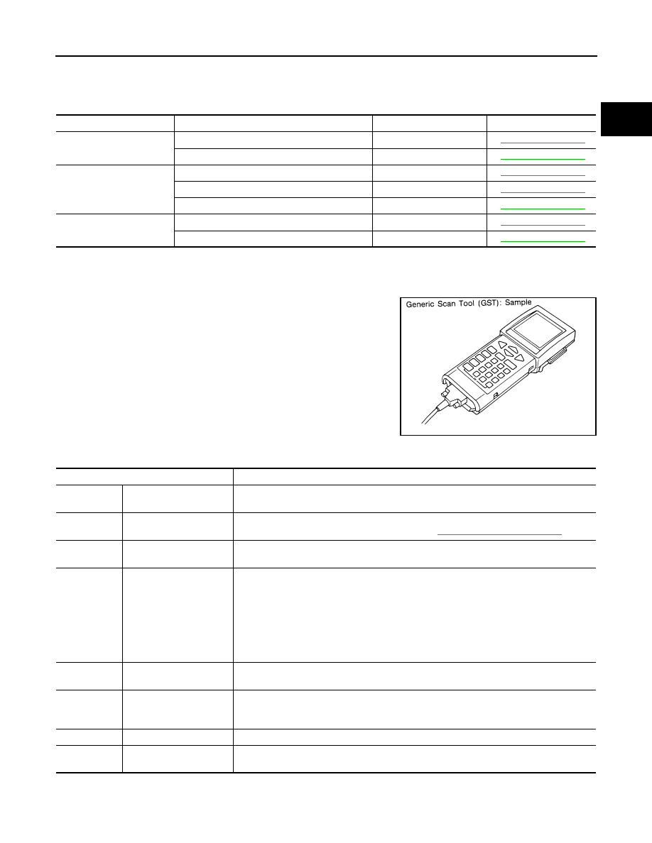
DESCRIPTION
Generic Scan Tool (OBD II scan tool) complying with SAE J1978/
ISO 15031-4 has several functions explained below.
ISO15765-4 is used as the protocol.
The name “GST” or “Generic Scan Tool” is used in this service man-
ual.
FUNCTION
INSPECTION PROCEDURE
1.
Turn ignition switch OFF.
Test mode
Test item
Corresponding DTC No.
Reference page
EGR SYSTEM
EGR SYSTEM P0400
P0400
EGR SYSTEM P1402
P1402
HO2S2
HO2S2 (B1) P1146
P0138
HO2S2 (B1) P1147
P0137
HO2S2 (B1) P0139
P0139
A/F SEN1
A/F SEN1 (B1) P1278/P1279
P0133
A/F SEN1 (B1) P1276
P0130
SEF139P
Diagnostic Service
Function
Service $01
READINESS TESTS
This diagnostic service gains access to current emission-related data values, including an-
alog inputs and outputs, digital inputs and outputs, and system status information.
Service $02
(FREEZE DATA)
This diagnostic service gains access to emission-related data value which were stored by
ECM during the freeze frame. For details, refer to
EC-45, "Diagnosis Description"
.
Service $03
DTCs
This diagnostic service gains access to emission-related power train trouble codes which
were stored by ECM.
Service $04
CLEAR DIAG INFO
This diagnostic service can clear all emission-related diagnostic information. This in-
cludes:
• Clear number of diagnostic trouble codes (Service $01)
• Clear diagnostic trouble codes (Service $03)
• Clear trouble code for freeze frame data (Service $01)
• Clear freeze frame data (Service $02)
• Reset status of system monitoring test (Service $01)
• Clear on board monitoring test results (Service $06 and $07)
Service $06
(ON BOARD TESTS)
This diagnostic service accesses the results of on board diagnostic monitoring tests of
specific components/systems that are not continuously monitored.
Service $07
(ON BOARD TESTS)
This diagnostic service enables the off board test drive to obtain test results for emission-
related powertrain components/systems that are continuously monitored during normal
driving conditions.
Service $08
—
This diagnostic service is not applicable on this vehicle.
Service $09
(CALIBRATION ID)
This diagnostic service enables the off-board test device to request specific vehicle infor-
mation such as Vehicle Identification Number (VIN) and Calibration IDs.
EC-64
< SYSTEM DESCRIPTION >
[HR12DE (TYPE 1)]
ON BOARD DIAGNOSTIC (OBD) SYSTEM
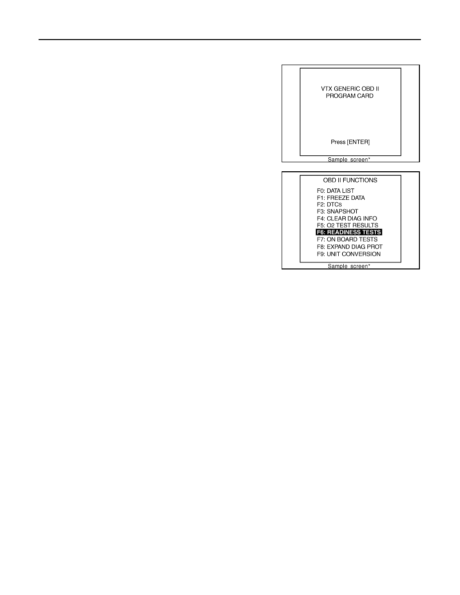
2.
Connect “GST” to data link connector, which is located under dash panel near the hood opener handle.
3.
Turn ignition switch ON.
4.
Enter the program according to instruction on the screen or in
the operation manual.
(*: Regarding GST screens in this section, sample screens are
shown.)
5.
Perform each diagnostic mode according to each service proce-
dure.
For further information, see the GST Operation Manual of
the tool maker.
SEF398S
SEF416S
Нет комментариевНе стесняйтесь поделиться с нами вашим ценным мнением.
Текст