Nissan March K13. Manual — part 101
RADIATOR CORE SUPPORT
DLK-115
< REMOVAL AND INSTALLATION >
[WITH INTELLIGENT KEY SYSTEM]
C
D
E
F
G
H
I
J
L
M
A
B
DLK
N
O
P
6.
Remove radiator upper seal fixing clips.
7.
Remove fixing clips of radiator side seal (LH and RH) upper side.
8.
Remove crash zone sensor. Refer to
SR-25, "Removal and Installation"
.
9.
Disconnect all harness.
10. Remove radiator reservoir tank mounting bolt.
11. Remove front bumper fascia upper side fixing clips.
12. Remove radiator core support upper mounting bolts.
13. Lift up upper part of front bumper fascia.
14. Lift up right side of radiator core support upper and remove radi-
ator core support upper by pulling it out toward the vehicle right
side.
Installation
Install in the reverse order of removal.
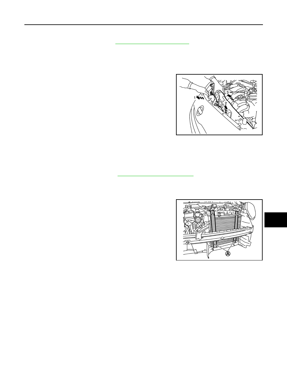
RADIATOR CORE SUPPORT LOWER
Removal
1.
Remove front bumper fascia. Refer to
EXT-11, "Removal and Installation"
2.
Remove radiator upper seal fixing clips, and then radiator upper seal from radiator core support upper.
3.
Remove fixing clips of radiator side seal (LH and RH) under side.
4.
Remove clips of fender protector.
5.
Use a belts (A) to suspend it to prevent it from falling.
CAUTION:
Never damage radiator and condenser.
6.
Remove mounting bolts, and then remove radiator core support lower.
Installation
Install in the reverse order of removal.
JMKIA5294ZZ
JMKIA5295ZZ
DLK-116
< REMOVAL AND INSTALLATION >
[WITH INTELLIGENT KEY SYSTEM]
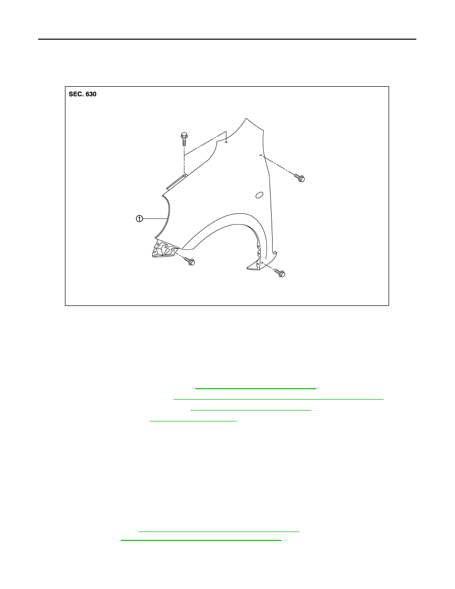
FRONT FENDER
FRONT FENDER
Exploded View
INFOID:0000000005948973
Removal and Installation
INFOID:0000000005948974
CAUTION:
Use a shop cloth to protect the body from being damaged during removal and installation.
REMOVAL
1.
Remove front combination lamp. Refer to
EXL-90, "Removal and Installation"
.
2.
Remove fender protector. Refer to
EXT-17, "FENDER PROTECTOR : Removal and Installation"
3.
Remove side turn signal lamp. Refer to
EXL-95, "Removal and Installation"
4.
Remove front fender cover.
5.
Remove mounting bolts, and then remove front fender.
CAUTION:
An viscous urethane foam is installed on the back surface of front fender. When removing the
front fender, be careful to not deform the front fender while performing the procedure and remov-
ing the viscous urethane foam a little at a time.
INSTALLATION
Note the following items, and install in the reverse order of removal.
CAUTION:
• After installation, apply the touch-up paint (the body color) onto the head of front fender mounting
bolts.
• After installation, adjust the following part.
- Hood assembly: Refer to
DLK-112, "HOOD ASSEMBLY : Adjustment"
.
- Front door: Refer to
DLK-118, "DOOR ASSEMBLY : Adjustment"
1.
Front fender assembly
JMKIA5296ZZ
FRONT DOOR
DLK-117
< REMOVAL AND INSTALLATION >
[WITH INTELLIGENT KEY SYSTEM]
C
D
E
F
G
H
I
J
L
M
A
B
DLK
N
O
P
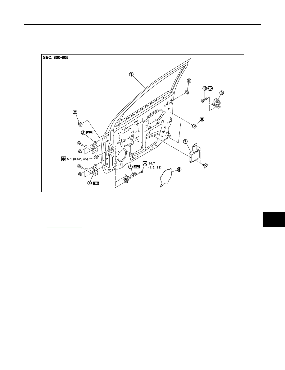
FRONT DOOR
Exploded View
INFOID:0000000005948975
DOOR ASSEMBLY
DOOR ASSEMBLY : Removal and Installation
INFOID:0000000005948976
CAUTION:
• Perform work with 2 workers, because of its heavy weight.
• When removing and installing front door assembly, support door with a jack and shop cloth to pro-
tect door and body.
REMOVAL
1.
Remove mounting bolts of door check link on the vehicle.
2.
Remove front door harness grommet, and then pull out the harness from the vehicle.
3.
Disconnect front door harness connector.
4.
Remove door hinge mounting nuts (door side), and then remove door assembly.
INSTALLATION
Note the following items, and install in the reverse order of removal.
CAUTION:
• Apply anticorrosive agent onto the mounting surface.
• Check front door open/close, lock/unlock operation after installation.
• Check door hinge rotating part for poor lubrication. If necessary, apply body grease.
1.
Front door panel
2.
Grommet (driver side only)
3.
Door hinge (upper)
4.
Door hinge (lower)
5.
Door check link
6.
Sealing screen (lower)
7.
Door pad
8.
Bumper rubber
9.
Door striker
10. TORX bolt
11.
Grommet
Refer to
JMKIA5317GB
DLK-118
< REMOVAL AND INSTALLATION >
[WITH INTELLIGENT KEY SYSTEM]
FRONT DOOR
• After installation, perform the fitting adjustment. Refer to
DLK-118, "DOOR ASSEMBLY : Adjust-
• After installation, apply touch-up paint (the body color) onto the head of door hinge mounting nuts.
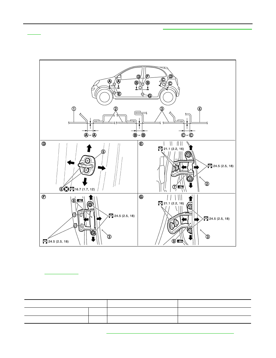
DOOR ASSEMBLY : Adjustment
INFOID:0000000005948977
Check the clearance and surface height between front door and each part by visually and touching.
If the clearance and the surface height are out of specification, adjust them according to the procedures
shown below.
Unit: mm (in)
1.
Remove fender protector. Refer to
EXT-17, "FENDER PROTECTOR : Removal and Installation"
.
2.
Loosen door hinge mounting nuts on door side.
1.
Front fender
2.
Front door
3.
Rear door
4.
Body side outer
5.
Door striker
6.
TORX bolt
7.
Front door hinge
8.
Rear door hinge (upper)
9.
Rear door hinge (lower)
Refer to
for symbols in the figure.
Portion
Clearance
Surface height
Front fender – Front door
A – A
3.7 – 5.7 (0.146 – 0.224)
- 1.0 – 1.0 (- 0.039 – 0.039)
Front door – Rear door
B – B
3.7 – 5.7 (0.146 – 0.224)
- 1.0 – 1.0 (- 0.039 – 0.039)
JMKIA5318GB
Нет комментариевНе стесняйтесь поделиться с нами вашим ценным мнением.
Текст