Nissan March K13. Manual — part 488
PCS-34
< SYSTEM DESCRIPTION >
[IPDM E/R (WITHOUT I-KEY)]
SYSTEM
IPDM E/R outputs power generation command signal (PWM signal) to the alternator according to the status of
the power generation command value signal received from ECM via CAN communication. Refer to
"POWER GENERATION VOLTAGE VARIABLE CONTROL SYSTEM : System Diagram"
.
SIGNAL BUFFER SYSTEM
SIGNAL BUFFER SYSTEM : System Diagram
INFOID:0000000005914143
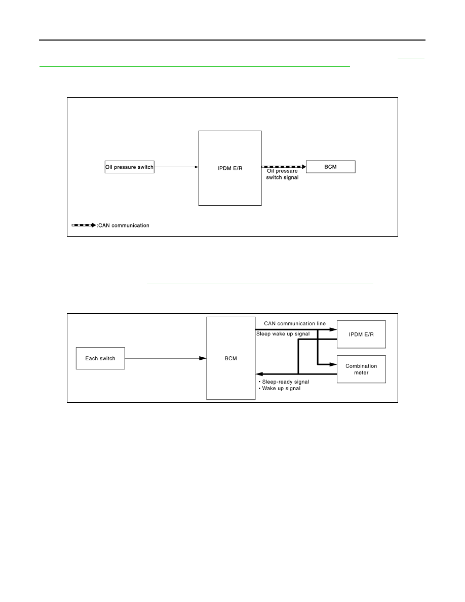
SIGNAL BUFFER SYSTEM : System Description
INFOID:0000000005914144
IPDM E/R reads the status of the oil pressure switch and transmits the oil pressure switch signal to BCM via
CAN communication. Refer to
MWI-10, "OIL PRESSURE WARNING LAMP : System Diagram"
.
POWER CONSUMPTION CONTROL SYSTEM
POWER CONSUMPTION CONTROL SYSTEM : System Diagram
INFOID:0000000006053651
POWER CONSUMPTION CONTROL SYSTEM : System Description
INFOID:0000000005914146
OUTLINE
• IPDM E/R incorporates a power consumption control function that reduces the power consumption accord-
ing to the vehicle status.
• IPDM E/R changes its status (control mode) with the sleep wake up signal received from BCM via CAN com-
munication.
Normal mode (wake-up)
- CAN communication is normally performed with other control units.
- Individual unit control by IPDM E/R is normally performed.
Low power consumption mode (sleep)
- Low power consumption control is active.
- CAN transmission is stopped.
SLEEP MODE ACTIVATION
JMMIA0402GB
JPMIA0731GB
PCS
SYSTEM
PCS-35
< SYSTEM DESCRIPTION >
[IPDM E/R (WITHOUT I-KEY)]
C
D
E
F
G
H
I
J
K
L
B
A
O
P
N
• IPDM E/R judges that the sleep-ready conditions are fulfilled when the ignition switch is OFF and none of the
conditions below are present. Then it transmits a sleep-ready signal (ready) to BCM via CAN communica-
tion.
- Outputting signals to actuators
- Switches or relays operating
- Output requests are being received from control units via CAN communication.
• IPDM E/R stops CAN communication and enters the low power consumption mode when it receives a sleep
wake up signal (sleep) from BCM and the sleep-ready conditions are fulfilled.
WAKE-UP OPERATION
• IPDM E/R changes from the low power consumption mode to the normal mode when it receives a sleep
wake-up signal (wake up) from BCM or any of the following conditions is fulfilled. In addition, it transmits a
sleep-ready signal (not-ready) to BCM via CAN communication to report the CAN communication start.
- Ignition switch ON
- An output request is received from a control unit via CAN communication.

PCS-36
< SYSTEM DESCRIPTION >
[IPDM E/R (WITHOUT I-KEY)]
DIAGNOSIS SYSTEM (IPDM E/R)
DIAGNOSIS SYSTEM (IPDM E/R)
Diagnosis Description
INFOID:0000000005914147
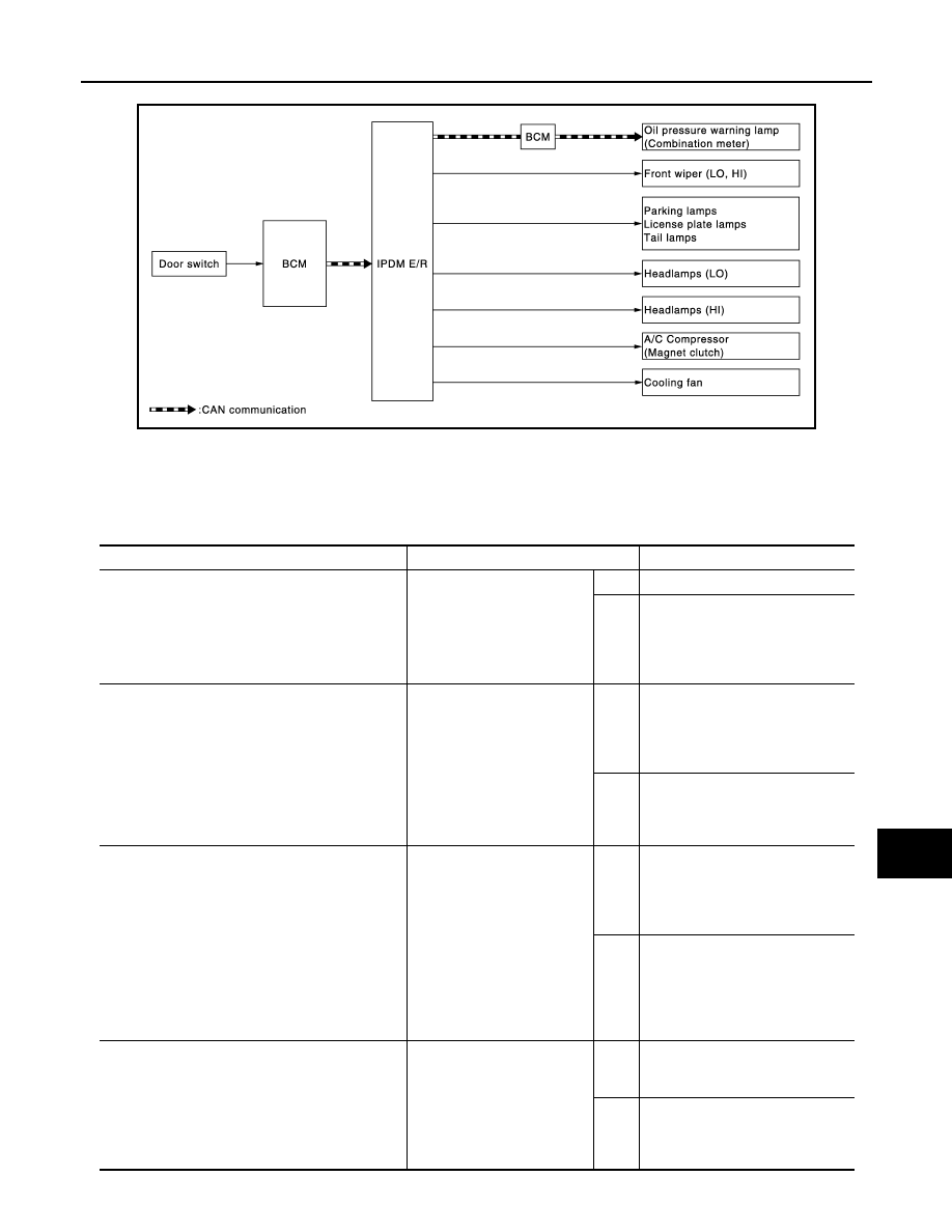
AUTO ACTIVE TEST
Description
In auto active test, the IPDM E/R sends a drive signal to the following systems to check their operation.
• Oil pressure warning lamp
• Front wiper (LO, HI)
• Parking lamps
• License plate lamps
• Tail lamps
• Headlamps (LO, HI)
• A/C compressor (magnet clutch)
• Cooling fan
Operation Procedure
CAUTION:
Never perform auto active test in the following conditions.
• Engine is running
• CONSULT-III is connected
1.
Close the hood and lift the wiper arms from the windshield. (Prevent windshield damage due to wiper
operation)
NOTE:
When auto active test is performed with hood opened, sprinkle water on windshield beforehand.
2.
Turn the ignition switch OFF.
3.
Turn the ignition switch ON, and within 20 seconds, press the driver door switch 10 times. Then turn the
ignition switch OFF.
CAUTION:
Close passenger door.
4.
Turn the ignition switch ON within 10 seconds. After that the horn sounds once and the auto active test
starts.
CAUTION:
Engine starts when ignition switch is turned ON while brake pedal is depressed.
5.
The oil pressure warning lamp starts blinking when the auto active test starts.
6.
After a series of the following operations is repeated 3 times, auto active test is completed.
NOTE:
• When auto active test has to be cancelled halfway through test, turn the ignition switch OFF.
• When auto active test is not activated, door switch may be the cause. Check door switch. Refer to
XX-XX,
"*****"
.
Inspection in Auto Active Test
When auto active test is actuated, the following operation sequence is repeated 3 times.
Operation
sequence
Inspection location
Operation
1
Oil pressure warning lamp
Blinks continuously during operation of auto active test
2
Front wiper
LO for 5 seconds
→
HI for 5 seconds
3
• Parking lamps
• License plate lamps
• Tail lamps
10 seconds
4
Headlamps
LO for 10 seconds
→
HI ON
⇔
OFF 5 times
5
A/C compressor (magnet clutch)
ON
⇔
OFF 5 times
6
Cooling fan
LO for 5 seconds
→
MID for 3 seconds
→
HI for 2 seconds
PCS
DIAGNOSIS SYSTEM (IPDM E/R)
PCS-37
< SYSTEM DESCRIPTION >
[IPDM E/R (WITHOUT I-KEY)]
C
D
E
F
G
H
I
J
K
L
B
A
O
P
N
Concept of Auto Active Test
• IPDM E/R starts the auto active test with the door switch signals transmitted by BCM via CAN communica-
tion. Therefore, the CAN communication line between IPDM E/R and BCM is considered normal if the auto
active test starts successfully.
• The auto active test facilitates troubleshooting if any systems controlled by IPDM E/R cannot be operated.
Diagnosis chart in auto active test mode
JMMIA0355GB
Symptom
Inspection contents
Possible cause
Any of the following components do not operate
• Parking lamps
• License plate lamps
• Tail lamps
• Headlamps (HI, LO)
• Front wiper (HI, LO)
Perform auto active test.
Does the applicable system
operate?
YES
BCM signal input circuit
NO
• Lamp or motor
• Lamp or motor ground circuit
• Harness or connector between
IPDM E/R and applicable system
• IPDM E/R
A/C compressor does not operate
Perform auto active test.
Does the magnet clutch oper-
ate?
YES
• BCM signal input circuit
• CAN communication signal be-
tween BCM and ECM
• CAN communication signal be-
tween ECM and IPDM E/R
NO
• Magnet clutch
• Harness or connector between
IPDM E/R and magnet clutch
• IPDM E/R
Oil pressure warning lamp does not operate
Perform auto active test.
Does the oil pressure warning
lamp blink?
YES
• Harness or connector between
IPDM E/R and oil pressure
switch
• Oil pressure switch
• IPDM E/R
NO
• CAN communication signal be-
tween IPDM E/R and BCM
• CAN communication signal be-
tween BCM and combination
meter
• Combination meter
Cooling fan does not operate
Perform auto active test.
Does the cooling fan operate?
YES
• ECM signal input circuit
• CAN communication signal be-
tween ECM and IPDM E/R
NO
• Cooling fan motor
• Harness or connector between
IPDM E/R and cooling fan motor
• IPDM E/R
Нет комментариевНе стесняйтесь поделиться с нами вашим ценным мнением.
Текст