Nissan March K13. Manual — part 486

PCS-26
< DTC/CIRCUIT DIAGNOSIS >
[IPDM E/R (WITH I-KEY)]
B2099 IGNITION RELAY OFF STUCK
B2099 IGNITION RELAY OFF STUCK
Description
INFOID:0000000005914132
• IPDM E/R operates the ignition relay when it receives an ignition switch ON signal from BCM via CAN com-
munication.
• Turn the ignition relay OFF by pressing the push-button ignition switch once when the vehicle speed is 4 km/
h (2.5 MPH) or less.
• Turn the ignition relay OFF with the following operation when the vehicle speed is more than 4 km/h (2.5
MPH) or when an abnormal condition occurs in CAN communication from the combination meter (Emer-
gency OFF)
- Press and hold the push-button ignition switch for 2 seconds or more.
- Press the push-button ignition switch 3 times within 1.5 seconds.
NOTE:
The ignition relay does not turn ON for 3 seconds after emergency OFF even if the push-button ignition switch
is pressed.
DTC Logic
INFOID:0000000005914133
DTC DETECTION LOGIC
NOTE:
When IPDM E/R power supply voltage is low (Approx. 7 - 8 V for about 1 second), the “DTC: B2099” may be detected.
Diagnosis Procedure
INFOID:0000000005914134
1.
PERFORM SELF DIAGNOSIS
1.
Turn the ignition switch ON.
2.
Erase “Self Diagnostic Result”.
3.
Turn the ignition switch OFF.
4.
Turn the ignition switch ON. Check “Self Diagnostic Result” again.
Is DTC “B2099” displayed?
YES
>> Replace IPDM E/R. Refer to
PCS-28, "Removal and Installation"
NO
>> Refer to
GI-33, "Intermittent Incident"
.
DTC
CONSULT-III dis-
play description
DTC Detection Condition
Possible causes
B2099
IGN RELAY OFF
The ignition relay OFF is detected for 1 second at ignition switch ON
(CPU monitors the status at the contact and excitation coil circuits of
the ignition relay inside it)
Ignition relay malfunction
PCS
POWER SUPPLY AND GROUND CIRCUIT
PCS-27
< DTC/CIRCUIT DIAGNOSIS >
[IPDM E/R (WITH I-KEY)]
C
D
E
F
G
H
I
J
K
L
B
A
O
P
N
POWER SUPPLY AND GROUND CIRCUIT
Diagnosis Procedure
INFOID:0000000005914135
1.
CHECK FUSES AND FUSIBLE LINK
Check that the following IPDM E/R fuses or fusible links are not blown.
Is the fuse fusing?
YES
>> Replace the blown fuse or fusible link after repairing the affected circuit if a fuse or fusible link is
blown.
NO
>> GO TO 2.
2.
CHECK POWER SUPPLY CIRCUIT
1.
Turn the ignition switch OFF.
2.
Disconnect IPDM E/R connector.
3.
Check voltage between IPDM E/R harness connector and the ground.
Is the measurement value normal?
YES
>> GO TO 3.
NO
>> Repair the harness or connector.
3.
CHECK GROUND CIRCUIT
Check continuity between IPDM E/R harness connectors and the ground.
Does continuity exist?
YES
>> INSPECTION END
NO
>> Repair the harness or connector.
Signal name
Fuses and fusible link No.
Battery power supply
C (80 A)
D (60 A)
F (40 A)
(+)
(
−
)
Voltage
(Approx.)
IPDM E/R
Connector
Terminal
E9
1
Ground
Battery voltage
2
E11
32
IPDM E/R
Ground
Continuity
Connector
Terminal
E10
10
Existed
E14
55
PCS-28
< REMOVAL AND INSTALLATION >
[IPDM E/R (WITH I-KEY)]
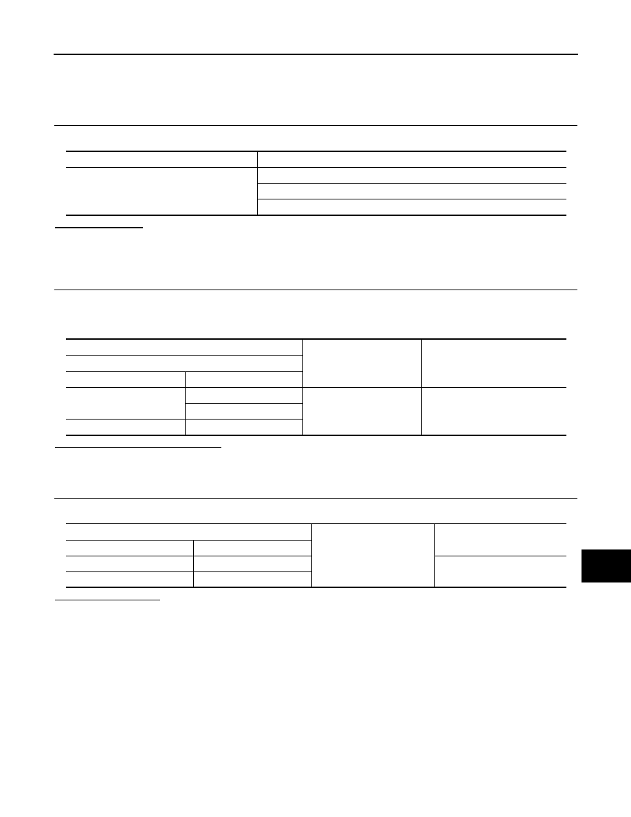
IPDM E/R
REMOVAL AND INSTALLATION
IPDM E/R
Exploded View
INFOID:0000000005914136
Removal and Installation
INFOID:0000000005914137
CAUTION:
IPDM E/R integrated relays are not serviceable parts, and must not be removed from the unit.
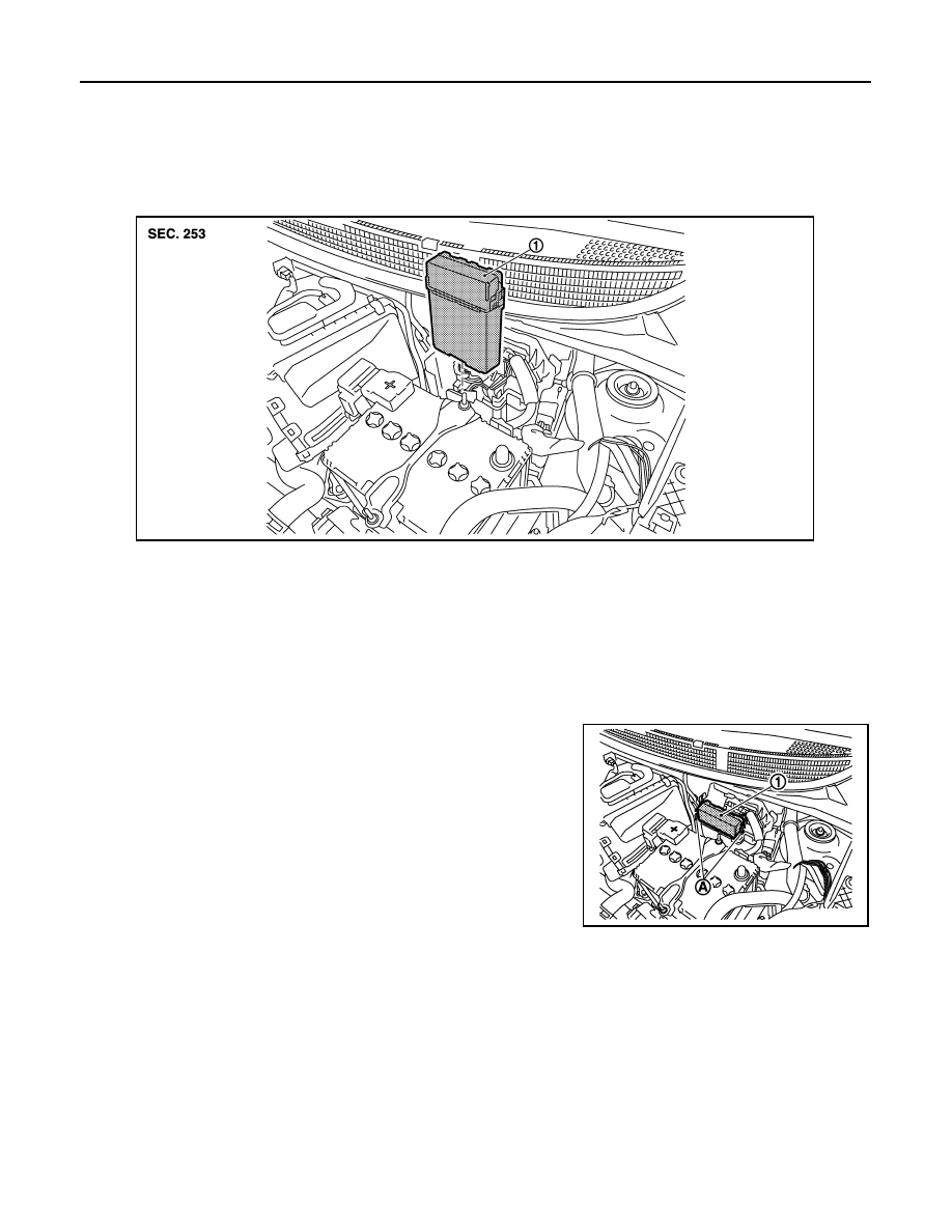
REMOVAL
1.
Disconnect the battery cable from the negative terminal.
2.
Remove the IPDM E/R (1) while disengaging both pawls (A) by
spreading them.
3.
Disconnect the harness connector and then remove the IPDM
E/R.
INSTALLATION
Install in the reverse order of removal.
1.
IPDM E/R
JMMIA0357ZZ
JMMIA0358ZZ
PCS
PRECAUTIONS
PCS-29
< PRECAUTION >
[IPDM E/R (WITHOUT I-KEY)]
C
D
E
F
G
H
I
J
K
L
B
A
O
P
N
PRECAUTION
PRECAUTIONS
Precaution for Supplemental Restraint System (SRS) "AIR BAG" and "SEAT BELT
PRE-TENSIONER"
INFOID:0000000005984313
The Supplemental Restraint System such as “AIR BAG” and “SEAT BELT PRE-TENSIONER”, used along
with a front seat belt, helps to reduce the risk or severity of injury to the driver and front passenger for certain
types of collision. Information necessary to service the system safely is included in the “SRS AIR BAG” and
“SEAT BELT” of this Service Manual.
WARNING:
• To avoid rendering the SRS inoperative, which could increase the risk of personal injury or death in
the event of a collision which would result in air bag inflation, all maintenance must be performed by
an authorized NISSAN/INFINITI dealer.
• Improper maintenance, including incorrect removal and installation of the SRS, can lead to personal
injury caused by unintentional activation of the system. For removal of Spiral Cable and Air Bag
Module, see the “SRS AIR BAG”.
• Do not use electrical test equipment on any circuit related to the SRS unless instructed to in this
Service Manual. SRS wiring harnesses can be identified by yellow and/or orange harnesses or har-
ness connectors.
PRECAUTIONS WHEN USING POWER TOOLS (AIR OR ELECTRIC) AND HAMMERS
WARNING:
• When working near the Air Bag Diagnosis Sensor Unit or other Air Bag System sensors with the
ignition ON or engine running, DO NOT use air or electric power tools or strike near the sensor(s)
with a hammer. Heavy vibration could activate the sensor(s) and deploy the air bag(s), possibly
causing serious injury.
• When using air or electric power tools or hammers, always switch the ignition OFF, disconnect the
battery, and wait at least 3 minutes before performing any service.
Нет комментариевНе стесняйтесь поделиться с нами вашим ценным мнением.
Текст