Nissan Qashqai (2022 year). Manual in english — page 9

JVI1617X
Example
Headlight beam select
To select the high beam function, push
the lever forward. The high beam lights
come on and the
light illuminates.
Pull the lever back to select the low beam.
Pulling and releasing the lever flashes the
headlight high beams on and off.
High beam assist
The high beam assist system will operate
when the vehicle is driven at speeds of
approximately 19 MPH (30 km/h) and
above. If an oncoming vehicle or leading
vehicle appears in front of your vehicle
when the headlight high beam is on, the
headlight will be switched to the low
beam automatically.
Precautions on high beam assist:
WARNING
.
The high beam assist system is a
convenience but it is not a sub-
stitute for safe driving operation.
The driver should remain alert at
all times, ensure safe driving
practices and switch the high
beams and low beam manually
when necessary.
.
The high beam or low beam may
not switch automatically under
the following conditions. Switch
the high beam and low beam
manually.
— During bad weather (rain, fog,
snow, wind, etc.).
— When a light source similar to
a headlight or tail light is in
the vicinity of the vehicle.
— When the headlights of the
oncoming vehicle or the lead-
ing vehicle are turned off,
when the color of the light is
affected due to foreign mate-
rials on the lights, or when the
light beam is out of position.
— When there is a sudden, con-
tinuous change in brightness.
— When driving on a road that
passes over rolling hills, or a
road that has level differ-
ences.
— When driving on a road with
many curves.
— When a sign or mirror-like
surface is reflecting intense
light towards the front of the
vehicle.
— When the container, etc. being
towed by a leading vehicle is
reflecting intense light.
— When a headlight on your
vehicle is damaged or dirty.
— When the vehicle is leaning at
an angle due to a punctured
tire, being towed, etc.
Instruments and controls
2-55
-------------------------------------------------------------------------------------------------------------------------------------------------------------

2-56
Instruments and controls
.
The timing of switching the low
beam and high beam may
change under the following situa-
tions.
— The brightness of the head-
lights of the oncoming vehicle
or leading vehicle.
— The movement and direction
of the oncoming vehicle and
the leading vehicle.
— When only one light on the
oncoming vehicle or the lead-
ing vehicle is illuminated.
— When the oncoming vehicle or
the leading vehicle is a two-
wheeled vehicle.
— Road conditions (incline,
curve, the road surface, etc.).
— The number of passengers
and the amount of cargo.
JVI1621X
Type A
WAC0414X
Type B
High beam assist operations:
To activate the high beam assist system,
turn the headlight switch to the AUTO
position
or
position (Type B) and
push the lever forward
(high beam
position). The high beam assist indicator
light in the meter will illuminate while the
headlights are turned on.
If the high beam assist indicator light
does not illuminate in the above condi-
tion, it may indicate that the system is not
functioning properly. It is recommended
you have the system checked by a
NISSAN dealer.
When the vehicle speed lowers to less
than approximately 13 MPH (20 km/h), the
headlight remains the low beam.
To turn off the high beam assist system,
turn the headlight switch to the
position or select the low beam position
by placing the lever in the neutral posi-
tion.
-------------------------------------------------------------------------------------------------------------------------------------------------------------

WAC0198X
Ambient image sensor maintenance:
The ambient image sensor
for the high
beam assist system is located in front of
the inside mirror. To keep the proper
operation of the high beam assist system
and prevent a system malfunction, be
sure to observe the following:
.
Always keep the windshield clean.
.
Do not attach a sticker (including
transparent material) or install an
accessory near the ambient image
sensor.
.
Do not strike or damage the areas
around the ambient image sensor. Do
not touch the sensor lens that is
located on the ambient image sensor.
If the ambient image sensor is damaged
due to an accident, it is recommended
you contact a NISSAN dealer.
Battery saver system
.
When the headlight switch is in the
or
position while the ignition
switch is in the ON position, the lights
will automatically turn off within a
period of time after the ignition switch
has been placed in the OFF position.
.
When the headlight switch remains in
the
or
position after the lights
automatically turn off, the lights will
turn on when the ignition switch is
placed in the ON position.
CAUTION
.
When you turn on the headlight
switch again after the lights auto-
matically turn off, the lights will
not turn off automatically. Be
sure to turn the light switch to
the OFF (if so equipped) or the
AUTO position when you leave
the vehicle for extended periods
of time, otherwise the battery will
be discharged.
.
Never leave the light switch on
when the engine is not running
for extended periods of time even
if the headlights turn off auto-
matically.
Daytime Running Light (DRL) sys-
tem
Type A:
The LED portion of the headlights auto-
matically illuminate at 100% intensity
when the engine is started and the
parking brake released. The LED Daytime
Running Light (DRL) operate with the
headlight switch in the AUTO (when the
headlights are off), OFF or
position.
When you turn the headlight switch to
the
position for full illumination, the
LED lights switch from LED DRL to the
park function.
If the parking brake is applied before the
engine is started, the LED DRL do not
illuminate. The LED DRL illuminate when
the parking brake is released. The LED
DRL will remain on until the ignition
switch is placed in the OFF position.
It is necessary at dusk to turn the head-
light switch ON for interior controls and
switches to illuminate, as those remain
OFF while the switch is in the OFF
position.
Instruments and controls
2-57
-------------------------------------------------------------------------------------------------------------------------------------------------------------

2-58
Instruments and controls
WARNING
When the LED DRL system is active,
tail lights on your vehicle are not on.
It is necessary at dusk to turn on
your headlights. Failure to do so
could cause an accident injuring
yourself and others.
Type B:
The LED portion of the headlights auto-
matically illuminate at 100% intensity
when the engine is started and the
parking brake released. The DRL operate
with the headlight switch in the AUTO
position or
position, the headlight
must be off. When you turn the headlight
switch to the
position for full illumi-
nation, the LED lights switch from LED
DRL to the park function.
If the parking brake is applied before the
engine is started, the LED DRL do not
illuminate. The LED DRL illuminate when
the parking brake is released. The LED
DRL will remain on until the ignition
switch is placed in the OFF position or
the headlight turns on.
JVI1591X
Example
TURN SIGNAL SWITCH
Turn signal
Move the lever up or down to signal the
turning direction. When the turn is com-
pleted, the turn signals cancel automati-
cally.
Lane change signal
Move the lever up or down until the turn
signal begins to flash, but the lever does
not latch, to signal a lane change. Hold
the lever until the lane change is com-
pleted.
Move the lever up or down until the turn
signal begins to flash, but the lever does
not latch, and release the lever. The turn
signal will automatically flash three times.
Choose the appropriate method to signal
a lane change based on road and traffic
conditions.
-------------------------------------------------------------------------------------------------------------------------------------------------------------

JVI0980X
Example
FOG LIGHT SWITCH (if so equipped)
To turn the fog lights on, turn the head-
light switch to the
position, then turn
the fog light switch to the
position.
To turn the fog lights on with the head-
light switch in the AUTO position or
position (Type B), the headlights must be
on, then turn the fog light switch to the
position.
To turn them off, turn the fog light switch
to the OFF position.
The headlights must be on for the fog
lights to operate. The fog lights automa-
tically turn off when the high beam
headlights are selected.
JVI1569X
To sound the horn, push the center pad
area of the steering wheel.
WARNING
Do not disassemble the horn. Doing
so could affect proper operation of
the supplemental front air bag sys-
tem. Tampering with the supple-
mental front air bag system may
result in serious personal injury.
JVI1592X
The heated steering wheel system is
designed to operate only when the sur-
face temperature of the steering wheel is
below 68°F (20°C).
Push the heated steering wheel switch to
warm the steering wheel after the engine
starts. The indicator light on the switch
will illuminate.
If the surface temperature of the steering
wheel is below 68°F (20°C), the system will
heat the steering wheel and cycle off and
on to maintain a temperature above 68°F
(20°C). The indicator light will remain on
as long as the system is on.
Push the switch again to turn the heated
steering wheel system off manually. The
Instruments and controls
2-59
HORN
HEATED STEERING WHEEL (if so equipped)
-------------------------------------------------------------------------------------------------------------------------------------------------------------
2-60
Instruments and controls
indicator light will turn off.
NOTE:
If the surface temperature of the steer-
ing wheel is above 68°F (20°C) when the
switch is turned on, the system will not
heat the steering wheel. This is not a
malfunction.
WARNING
Do not use or allow occupants to use
the seat heater if you or the occu-
pants cannot monitor elevated seat
temperatures or have an inability to
feel pain in body parts that contact
the seat. Use of the seat heater by
such people could result in serious
injury.
CAUTION
.
The battery could run down if the
seat heater is operated while the
engine is not running.
.
Do not use the seat heater for
extended periods or when no one
is using the seat.
.
Do not put anything on the seat
which insulates heat, such as a
blanket, cushion, seat cover, etc.
Otherwise, the seat may become
overheated.
.
Do not place anything hard or
heavy on the seat or pierce it with
a pin or similar object. This may
result in damage to the heater.
.
Any liquid spilled on the heated
seat should be removed immedi-
ately with a dry cloth.
.
When cleaning the seat, never use
gasoline, thinner, or any similar
materials.
.
If any malfunctions are found or
the heated seat does not operate,
turn the switch off and have the
system checked. It is recom-
mended you visit a NISSAN dealer
for this service.
HEATED SEATS (if so equipped)
-------------------------------------------------------------------------------------------------------------------------------------------------------------

JVR0322X
The seats are warmed by built-in heaters.
The switches located on the center con-
sole can be operated independently of
each other.
1. Start the engine.
2. Select heat range.
For high-speed heating, push the HI
(High) side of the switch.
For low-speed heating, push the LO
(Low) side of the switch.
The indicator light on the switch
will
illuminate when the heater is on.
3. To turn off the heater, return the
switch to the level position. Make sure
the indicator light goes off.
The heater is controlled by a thermo-
stat, automatically turning the heater
on and off. The indicator light will
remain on as long as the switch is on.
When the vehicle’s interior is warmed,
or before you leave the vehicle, be
sure to turn off the switch.
JVI1593X
The dynamic driver assistance switch is
used to temporarily turn on and off the
Intelligent Lane Intervention (I-LI) system.
The I-LI system must be turned on with
the dynamic driver assistance switch
every time the ignition is placed in the
ON position.
When the dynamic driver assistance
switch is turned off, the indicator
on
the switch is off. The indicator will also be
off if the I-LI system is deactivated using
the vehicle information display.
The I-LI system warns the driver with an
indicator and a chime, and helps assist
the driver to return the vehicle to the
center of the traveling lane by applying
Instruments and controls
2-61
DYNAMIC DRIVER ASSISTANCE SWITCH
(models without ProPILOT assist)
-------------------------------------------------------------------------------------------------------------------------------------------------------------

2-62
Instruments and controls
the brakes to the left or right wheels
individually (for a short period of time). For
additional information, see “Intelligent
Lane Intervention (I-LI)” (P.5-40).
WAC0074X
The steering assist switch is used to
temporarily turn on and off the steering
assist system.
The steering assist system controls the
steering system to help keep your vehicle
near the center of the lane when driving.
For additional information, see “ProPILOT
assist” (P.5-64).
SIC4544
The vehicle should be driven with the
Vehicle Dynamic Control (VDC) system on
for most driving conditions.
If the vehicle is stuck in mud or snow, the
VDC system reduces the engine output to
reduce wheel spin. The engine speed will
be reduced even if the accelerator is
depressed to the floor. If maximum en-
gine power is needed to free a stuck
vehicle, turn the VDC system off.
To turn off the VDC system, push the VDC
OFF switch. The
indicator light will
illuminate.
STEERING ASSIST SWITCH (models
with ProPILOT assist)
VEHICLE DYNAMIC CONTROL (VDC)
OFF SWITCH
-------------------------------------------------------------------------------------------------------------------------------------------------------------
Push the VDC OFF switch again or restart
the engine to turn on the system. (See
“Vehicle Dynamic Control (VDC) system”
(P.5-131).)
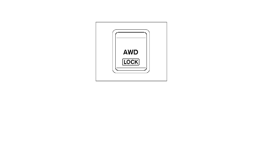
JVI1595X
The Intelligent 4x4 LOCK switch is located
on the instrument panel. The AWD LOCK
indicator light will illuminate when the
switch is turned on. For additional infor-
mation, refer to “Intelligent 4x4” (P.5-123).
Each time you push the switch, the AWD
mode will switch: AUTO
?
LOCK
?
AUTO.
The Rear Door Alert system functions
under certain conditions to indicate there
may be an object or passenger in the rear
seat(s). Check the seat(s) before exiting
the vehicle.
The Rear Door Alert system is initially
disabled. The driver can enable the sys-
tem using the vehicle information display.
For additional information, see “Vehicle
Settings” (P.2-23).
When the system is enabled:
.
The system is activated when a rear
door is opened and closed within 10
minutes of the vehicle being driven.
When the vehicle is started and the
system is activated, a visual message
appears in the vehicle information
display. For additional information,
see “44. Rear Door Alert is activated”
(P.2-36).
.
If a rear door is opened and closed but
the vehicle is not driven within ap-
proximately 10 minutes, the system
will not be activated. A rear door must
be opened and closed and the vehicle
is driven within 10 minutes for the
system to activate.
Instruments and controls
2-63
INTELLIGENT 4X4 LOCK SWITCH (if
so equipped)
REAR DOOR ALERT
-------------------------------------------------------------------------------------------------------------------------------------------------------------

2-64
Instruments and controls
When the Rear Door Alert system is
activated and a driver exits the vehicle
after arriving at a destination:
.
When the driver puts the vehicle in the
P (Park) position, a message appears
in the vehicle information display for
the driver to “Dismiss Message” or
“Disable Alert” if desired.
.
With the system enabled, when the
driver exits the vehicle, an audible alert
(horn sound) will occur unless a rear
door is opened and closed within a
short time to deactivate the alert.
.
If the doors are locked before the alert
is deactivated by opening a rear door,
the horn will sound.
.
If the system is activated but the
liftgate is opened before opening a
rear door, the horn will be delayed
until after the liftgate is closed.
.
If the audible horn alert occurs, a
message will also appear in the vehi-
cle information display that states,
“Check Back Seat for all articles”. For
additional information, see “45. Check
Back Seat For all articles” (P.2-36).
WARNING
.
If the driver selects “Disable
Alert”, no audible alert will be
provided regardless of rear door
open/close status.
.
There may be times when there is
an object or passenger in the rear
seat(s) but the audible alert does
not sound. For example, this may
occur if rear seat passengers
enter or exit the vehicle during a
trip.
.
The system does not directly
detect objects or passengers in
the rear seat(s). Instead, it can
detect when a rear door is
opened and closed, indicating
that there may be something in
the rear seat(s).
NOTE:
There may be times when the horn
sounds but there are no objects or
passengers in the rear seat(s).
For additional information, see “44. Rear
Door Alert is activated” (P.2-36).
JVS0185X
The ECO mode system helps to enhance
the fuel economy by controlling the
engine and CVT operation (for CVT mod-
els) automatically to avoid rapid accelera-
tion.
To turn on the ECO mode system, push
the ECO switch. The ECO mode indicator
appears on the meter.
To turn off the ECO mode, push the ECO
switch again. The ECO mode indicator will
turn off.
.
The ECO mode system cannot be
turned off while the accelerator pedal
is depressed even if the ECO switch is
pushed to OFF. Release the accelera-
tor pedal to turn off the ECO mode
ECO MODE SWITCH
-------------------------------------------------------------------------------------------------------------------------------------------------------------

system.
.
The ECO mode system will turn off
automatically if a malfunction occurs
in the system.
.
Turn off the ECO mode system when
acceleration is required such as when:
— driving with a heavy load of pas-
sengers or cargo in the vehicle
— driving on a steep uphill slope
WAC0077X
Instrument Panel
WAC0233X
Center Console Box
The power outlet is located in the instru-
ment panel and center console box.
CAUTION
.
The outlet and plug may be hot
during or immediately after use.
.
Do not use with accessories that
exceed a 12 volt, 120W (10A)
power draw. Do not use double
adapters or more than one elec-
trical accessory.
.
Use power outlet with the engine
running to avoid discharging the
vehicle battery.
.
Avoid using power outlet when
the air conditioner, headlights or
rear window defroster is on.
.
This power outlet is not designed
for use with a cigarette lighter
unit.
.
Push the plug in as far as it will
go. If good contact is not made,
the plug may overheat or the
internal temperature fuse may
open.
.
Before inserting or disconnecting
a plug, be sure the electrical
accessory being used is turned
OFF.
Instruments and controls
2-65
POWER OUTLET
-------------------------------------------------------------------------------------------------------------------------------------------------------------
2-66
Instruments and controls
.
When not in use, be sure to close
the cap. Do not allow water or any
liquid to contact the outlet.
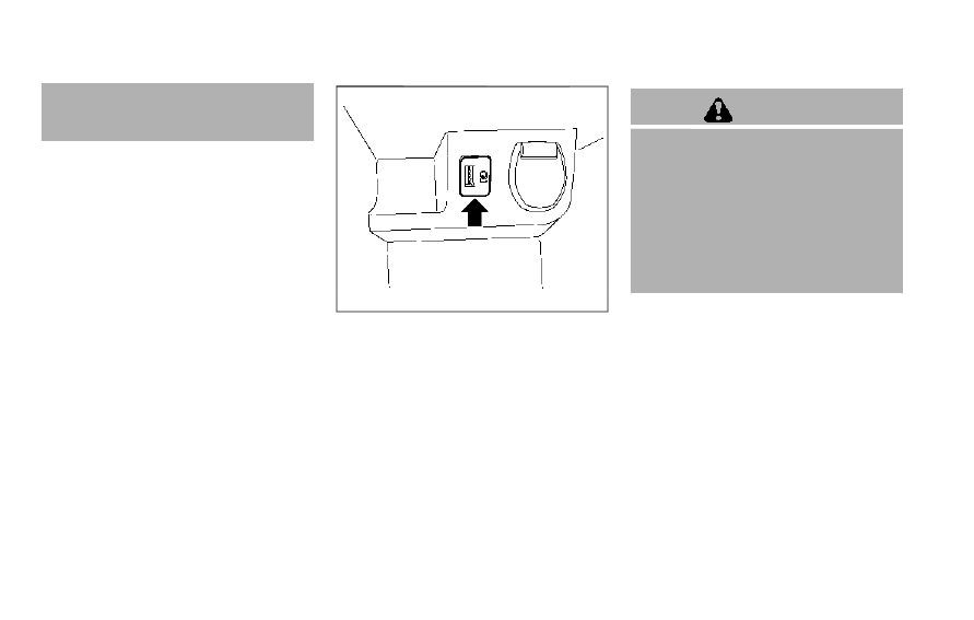
WAC0234X
USB (Universal Serial Bus) CHAR-
GING CONNECTOR
The USB charging connector is located in
the center console box.
The USB charging connector can be used
only for charging an external device.
Connect a USB device into the connector.
Charging will start automatically (max-
imum output up to 5 volt, 12W, 2.4A).
The external device will be charged con-
tinuously while the ignition switch is in
the ACC or ON position.
Some mobile devices cannot be charged
depending on their specifications.
CAUTION
.
Do not force a USB device into the
connector. Inserting the USB de-
vice tilted or up-side-down into
the connector may damage the
connector. Make sure that the
USB device is connected correctly
into the connector.
.
Do not use a reversible USB cable.
Using the reversible USB cable
may damage the connector.
-------------------------------------------------------------------------------------------------------------------------------------------------------------
EMERGENCY SUPPORT
NissanConnect® Services provides var-
ious services to support dealing with
emergencies of the subscribed vehicle
and the driver.
For example, in case of an illness or
serious injury, you can seek support by
pushing the in-vehicle Emergency Call
(SOS) button and connecting to Nissan-
Connect® Services. NissanConnect® Ser-
vices can specify the location of the
vehicle via GPS, and the information will
be sent to the police or other agencies as
needed.
For information about other NissanCon-
nect® Services emergency support re-
l a t e d s e r v i c e s , r e f e r t o t h e
NissanConnect® Services website or con-
tact the NissanConnect® Customer Sup-
port Line.
NissanConnect® Services website:
For U.S.
www.nissanusa.com/connect
For Canada
http://www.nissan.ca/nissanconnect
(English)
w w w . n i s s a n . c a / n i s s a n c o n n e c t / f r
(French)
NissanConnect® Customer Support Line:
1-855-426-6628
WARNING
.
Please note that the Automatic
Collision Notification service and
Emergency Call function cannot
be used in the following condi-
tions:
— Emergency functions and ser-
vices will not be available
without a paid subscription
to NissanConnect® Services.
— The NissanConnect® Services
network system is disabled.
— The vehicle moves outside the
service area where the TCU
(Telematics Control Unit) is
connected to the system.
— The vehicle is outside the area
where the cellular network
service is receivable.
— The vehicle is in a location
with poor signal reception
such as tunnels, underground
parking garages, behind
buildings or in mountainous
areas.
— The line is busy.
— The TCU (Telematics Control
Unit) or other systems of your
vehicle are not working prop-
erly.
— It may not be possible to
make an emergency call de-
pending on the severity of a
collision and/or emergency.
.
Park the vehicle in a safe location
and set the parking brake before
operating the Emergency Call
(SOS) button.
.
Only use this service in case of an
emergency. There may be a pen-
alty for inappropriate use of the
service.
.
Radio waves could adversely af-
fect electric medical equipment.
Individuals who use pacemakers
should contact the device manu-
facturer regarding any possible
effects before using the system.
.
The TCU (Telematics Control Unit)
antenna is installed inside the
upper central part of the instru-
ment panel. An occupant should
not get any closer to the antenna
than specified by the pacemaker
manufacturer. The radio waves
Instruments and controls
2-67
EMERGENCY CALL (SOS) BUTTON
(if so equipped)
-------------------------------------------------------------------------------------------------------------------------------------------------------------

2-68
Instruments and controls
from the TCU antenna may ad-
versely affect the operation of the
pacemaker while using the Nis-
sanConnect® Services.
WAC0510X
Making an emergency call
The design may vary from the illustra-
tions depending on the models and
specifications.
1. Push the Emergency Call (SOS) button.
2. When the line is connected, speak to
the Response Specialist.
If you want to cancel the emergency call,
push and hold the Emergency Call (SOS)
button for a few seconds.
The Emergency Call (SOS) button is lo-
cated near the map light.
NOTE:
.
When making an emergency call, be
sure the ignition switch is turned to
the ON position. The emergency call
cannot be activated while the igni-
tion switch is turned to the OFF
position.
.
After the Emergency Call (SOS) but-
ton is pushed, it may take some time
until the system initiates connec-
tion, depending on the technical
environment and whether the TCU
(Telematics Control Unit) is being
used by other services.
.
An indicator light on the Emergency
Call (SOS) button shows the readi-
ness of the emergency support sys-
tem. If the indicator light is not
illuminated, pushing the Emergency
Call (SOS) button does not connect
your vehicle to the Response Spe-
cialist.
The indicator light blinks while con-
nected to the NissanConnect® Ser-
vices Response Center.
.
Even when the indicator light is
illuminated, connection to the Nis-
sanConnect® Services Response
Center may not be possible. If this
occurs in an emergency situation,
contact the authorities by other
means.
-------------------------------------------------------------------------------------------------------------------------------------------------------------

.
To avoid disconnecting the line, do
not turn off the engine or the hybrid
system.
CUP HOLDERS
CAUTION
.
Avoid abrupt starting and braking
when the cup holder is being
used to prevent spilling the drink.
If the liquid is hot, it can scald you
or your passenger.
.
Use only soft cups in the cup
holder. Hard objects can injure
you in an accident.
JVI1601X
Center console
Front
Instruments and controls
2-69
STORAGE
-------------------------------------------------------------------------------------------------------------------------------------------------------------
2-70
Instruments and controls
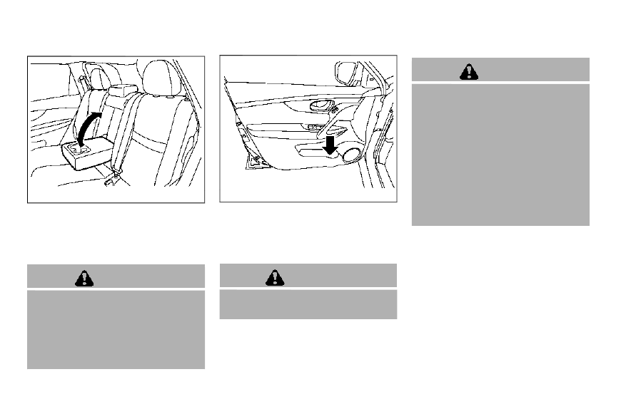
JVI0873X
Rear seat (if so equipped)
The rear cup holders are located in the
rear fold-down armrest.
SOFT BOTTLE HOLDERS
CAUTION
.
Do not use bottle holder for any
other objects that could be
thrown about in the vehicle and
possibly injure people during
sudden braking or an accident.
.
Do not use bottle holder for open
liquid containers.
JVI0884X
Door (front and rear)
FLEXIBLE LUGGAGE BOARDS (if so
equipped)
You can use the cargo area in diverse
ways using the flexible luggage boards.
WARNING
Do not put objects heavier than 110
lbs (50 kg) on the load floor.
CAUTION
.
Do not push the front edge of the
luggage board forcibly. Doing so
may cause the luggage board to
be tilted, resulting in personal
injury.
.
Do not handle the luggage board
forcibly as this may deform it.
.
While in the upper position, do
not recline the seatbacks.
.
Do not place cargo higher than
the seatbacks. In a sudden stop
or collision, unsecured cargo
could cause personal injury.
NOTE:
The diversity of the cargo area may be
restricted depending on the equipment
of each vehicle.
-------------------------------------------------------------------------------------------------------------------------------------------------------------
Нет комментариевНе стесняйтесь поделиться с нами вашим ценным мнением.
Текст