Qashqai J11. Transaxle & Transmission — part 5

TM-66
< UNIT DISASSEMBLY AND ASSEMBLY >
[6MT: RS6F94R]
REVERSE IDLER SHAFT AND GEAR
5.
Remove needle bearings (1) and washer from reverse idler
shaft.
Assembly
INFOID:0000000010288470
Note the following, and assemble in the reverse order of disassembly.
CAUTION:
• Never reuse snap ring.
• Make sure that snap ring is securely installed in the groove.
PCIB1761E

FINAL DRIVE
TM-67
< UNIT DISASSEMBLY AND ASSEMBLY >
[6MT: RS6F94R]
C
E
F
G
H
I
J
K
L
M
A
B
TM
N
O
P
FINAL DRIVE
Exploded View
INFOID:0000000010288471
.
Disassembly
INFOID:0000000010288472
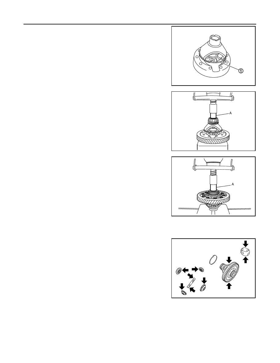
1.
Remove differential side bearing inner race (clutch housing side)
(1) using the drift (A) [SST: ST33061000] and a puller.
2.
Remove speedometer drive gear.
3.
Remove final gear mounting bolts (1), and then separate the
final gear (2) from differential case.
4.
Remove differential side bearing inner race (transaxle case
side) (1) using the drift (A) [Commercial service tool] and a suit-
able puller.
5.
Remove lock ring (1) from differential case.
6.
Remove pinion mate shaft, pinion mate gears, side gears and
thrust washer from differential case.
Assembly
INFOID:0000000010288473
1.
Install pinion mate shaft, pinion mate gears, side gears and thrust washer into differential case.
PCIB1767E
PCIB1766E
JPDIC0114ZZ
PCIB1764E
TM-68
< UNIT DISASSEMBLY AND ASSEMBLY >
[6MT: RS6F94R]
FINAL DRIVE
2.
Install lock ring (1) onto differential case.
CAUTION:
Make sure that lock ring is securely installed in the groove.
3.
Install final gear into differential case, and tighten final gear
mounting bolts to the specified torque.
4.
Install speedometer drive gear onto differential case.
5.
Press-fit the differential side bearing inner race (clutch housing
side) onto the differential case using the drift (A) [Commercial
service tool] and press.
CAUTION:
Replace differential side bearing inner race and differential
side bearing outer race as a set.
6.
Press-fit the differential side bearing inner race (transaxle case
side) onto the differential case using the drift (A) [Commercial
service tool] and press.
CAUTION:
Replace differential side bearing inner race and differential
side bearing outer race as a set.
Inspection
INFOID:0000000010288474
GEAR, WASHER, SHAFT AND CASE
Check side gears, thrust washer, pinion mate shaft, pinion mate
gears, lock ring and differential case. If necessary, replace with a
new one.
BEARING
PCIB1764E
JPDIC0115ZZ
JPDIC0116ZZ
PCIB0977J

FINAL DRIVE
TM-69
< UNIT DISASSEMBLY AND ASSEMBLY >
[6MT: RS6F94R]
C
E
F
G
H
I
J
K
L
M
A
B
TM
N
O
P
Check for bearing damage and rough rotation. If necessary, replace
with a new one.
CAUTION:
When replacing tapered roller bearing, replace outer and inner
races as a set.
SPD715

TM-70
< UNIT DISASSEMBLY AND ASSEMBLY >
[6MT: RS6F94R]
SHIFT FORK AND FORK ROD
SHIFT FORK AND FORK ROD
Exploded View
INFOID:0000000010288475
.
Disassembly
INFOID:0000000010288476
for disassembly procedure.
Assembly
INFOID:0000000010288477
for assembly procedure.
Inspection
INFOID:0000000010288478
FORK ROD AND SHIFT FORK
Check contact surface and sliding surface of fork rod and shift fork
for wear, damage, and bend. Replace if necessary.
SCIA7785E

SERVICE DATA AND SPECIFICATIONS (SDS)
TM-71
< SERVICE DATA AND SPECIFICATIONS (SDS)
[6MT: RS6F94R]
C
E
F
G
H
I
J
K
L
M
A
B
TM
N
O
P
SERVICE DATA AND SPECIFICATIONS (SDS)
SERVICE DATA AND SPECIFICATIONS (SDS)
General Specification
INFOID:0000000010288479
TRANSAXLE
FINAL GEAR
Engine type
HRA2DDT
K9K
MR20DD
Transaxle model
RS6F94R
Model code number
1KG0B (TL4 137)
JD50D (TL4 126)
4EA0A (TL4 129)
Number of speeds
6
Synchromesh type
Warner
Shift pattern
Gear ratio
1st
3.7273
2nd
1.9474
2.1053
3rd
1.3226
1.2258
1.5185
4th
0.975
0.8378
1.1714
5th
0.7632
0.6522
0.9143
6th
0.6383
0.5600
0.7674
Reverse
3.6865
Number of teeth
Input gear
1st
11
11
2nd
19
19
3rd
31
27
4th
40
37
35
5th
38
46
35
6th
47
50
43
Reverse
11
Main gear
1st
41
2nd
37
40
3rd
41
38
41
4th
39
31
41
5th
29
30
32
6th
30
28
33
Reverse
42
Reverse idler gear
Input/Output
28/29
Oil capacity
(Imp pt)
Approx. 2.0 (3-1/2)
Remarks
Reverse synchronizer
Installed
Triple-cone synchronizer
1st and 2nd
PCIB1769E

TM-72
< SERVICE DATA AND SPECIFICATIONS (SDS)
[6MT: RS6F94R]
SERVICE DATA AND SPECIFICATIONS (SDS)
Engine type
HRA2DDT
K9K
MR20DD
Transaxle model
RS6F94R
Model code number
1KG0B (TL4 137)
JD500 (TL4 126)
4EA0A (TL4 129)
Final gear ratio
4.2143
4.125
4.733
Number of teeth
Final gear/Pinion
12/59
16/66
16/71
Side gear/Pinion mate gear
13/10

M/T SYSTEM
TM-73
< SYSTEM DESCRIPTION >
[6MT: RS6F95R]
C
E
F
G
H
I
J
K
L
M
A
B
TM
N
O
P
SYSTEM DESCRIPTION
M/T SYSTEM
System Diagram
INFOID:0000000010428761
CROSS-SECTIONAL VIEW
1.
Mechanism housing
2.
6th main gear
3.
5th main gear
4.
4th main gear
5.
3rd main gear
6.
2nd main gear
7.
1st-2nd synchronizer assembly
8.
1st main gear
9.
Reverse gear sprocket
10. Mainshaft
11.
Input shaft
12. 6th input gear
E1DIA0333ZZ

TM-74
< SYSTEM DESCRIPTION >
[6MT: RS6F95R]
M/T SYSTEM
System Description
INFOID:0000000010428762
TRIPLE-CONE SYNCHRONIZER
Triple-cone synchronizer is used for the 1st and the 2nd gears to
reduce operating force of the control lever.
REVERSE GEAR NOISE PREVENTION FUNCTION (SYNCHRONIZING METHOD)
Reverse gear assembly consists of reverse input gear, return spring,
reverse baulk ring and reverse output gear. When the control lever is
shifted to the reverse position, the construction allows smooth shift
operation by stopping the reverse idler shaft rotation by frictional
force of synchronizer.
13. 5th-6th synchronizer assembly
14. 5th input gear
15. 4th input gear
16. 3rd-4th synchronizer assembly
17. 3rd input gear
18. 2nd input gear
19. Reverse gear sprocket
20. 1st main gear
21. Reverse gear shaft
22. Output seal
23. Differential assembly
24. Clutch housing
A.
Mechanism assembly
B.
Differential assembly
1
: 1st main gear
2
: 1st-2nd coupling sleeve
3
: Insert key
4
: Outer baulk ring
5
: 2nd main gear
6
: Synchronizer cone
7
: Inner baulk ring
8
: 1st-2nd synchronizer hub
SCIA7636E
1
: Reverse fork rod
2
: Reverse output gear
3
: Return spring
4
: Reverse baulk ring
5
: Reverse input gear
SCIA7621E

POSITION SWITCH
TM-75
< DTC/CIRCUIT DIAGNOSIS >
[6MT: RS6F95R]
C
E
F
G
H
I
J
K
L
M
A
B
TM
N
O
P
DTC/CIRCUIT DIAGNOSIS
POSITION SWITCH
BACK-UP LAMP SWITCH
BACK-UP LAMP SWITCH : Component Parts Location
INFOID:0000000010428763
BACK-UP LAMP SWITCH : Component Inspection
INFOID:0000000010428764
1.
CHECK BACK-UP LAMP SWITCH
Check continuity between position switch terminals with control lever
turned to 1st to 6th and reverse position.
Is the inspection result normal?
YES
>> INSPECTION END
NO
>> Replace position switch. Refer to
.
PARK/NEUTRAL POSITION (PNP) SWITCH
PARK/NEUTRAL POSITION (PNP) SWITCH : Component Parts Location
INFOID:0000000010428765
PARK/NEUTRAL POSITION (PNP) SWITCH : Component Inspection
INFOID:0000000010428766
1.
CHECK PARK/NEUTRAL POSITION (PNP) SWITCH
1
: Position switch
E1DIA0340ZZ
Terminals
Gear position
Continuity
1 – 2
Reverse
Existed
Except reverse
Not existed
E1DIA0344GB
1
: Position switch
E1DIA0340ZZ

TM-76
< DTC/CIRCUIT DIAGNOSIS >
[6MT: RS6F95R]
POSITION SWITCH
Check continuity between position switch terminals with control lever
turned to 1st to 6th and reverse position.
Is the inspection result normal?
YES
>> INSPECTION END
NO
>> Replace position switch. Refer to
Terminals
Gear position
Continuity
2 – 3
Neutral
Existed
Except neutral
Not existed
E1DIA0345GB

NOISE, VIBRATION AND HARSHNESS (NVH) TROUBLESHOOTING
TM-77
< SYMPTOM DIAGNOSIS >
[6MT: RS6F95R]
C
E
F
G
H
I
J
K
L
M
A
B
TM
N
O
P
SYMPTOM DIAGNOSIS
NOISE, VIBRATION AND HARSHNESS (NVH) TROUBLESHOOTING
NVH Troubleshooting Chart
INFOID:0000000010428767
Use the chart below to help you find the cause of the symptom. The numbers indicate the order of the inspec-
tion. If necessary, repair or replace these parts.
Reference page
SUSPECTED PARTS
(Possible cause)
OIL
(Oil
lev
e
l is
l
o
w
.)
OI
L (W
ro
ng
oi
l.
)
OIL
(Oil
lev
e
l is
h
igh
.)
GASKET
(Damaged)
OIL SEAL (W
orn or
damaged)
O-RING (W
orn
or
da
ma
ge
d)
SHIF
T CONTROL L
INKAGE
(W
o
rn)
SHIF
T FORK (W
o
rn)
GEAR (W
o
rn o
r da
m
age
d)
BEAR
ING
(W
orn
o
r
da
ma
ge
d)
BAUL
K
RING (W
orn
o
r da
ma
ge
d)
INSE
R
T
S
P
RING (Dam
ag
ed
)
Symptoms
Noise
1
2
3
3
Oil leakage
3
1
2
2
2
Hard to shift or will not shift
1
1
2
3
3
Jumps out of gear
1
2
2

TM-78
< PRECAUTION >
[6MT: RS6F95R]
PRECAUTIONS
PRECAUTION
PRECAUTIONS
Precaution for Procedure without Cowl Top Cover
INFOID:0000000010497457
When performing the procedure after removing cowl top cover, cover
the lower end of windshield with urethane, etc to prevent damage to
windshield.
Precautions for Removing Battery Terminal
INFOID:0000000010508550
• With the adoption of Auto ACC function, ACC power is automatically supplied by operating the intelligent key
or remote keyless entry or by opening/closing the driver side door. In addition, ACC power is supplied even
after the ignition switch is turned to the OFF position, i.e. ACC power is supplied for a certain fixed time.
• When disconnecting the 12V battery terminal, turn off the ACC
power before disconnecting the 12V battery terminal, observing
“How to disconnect 12V battery terminal” described below.
NOTE:
Some ECUs operate for a certain fixed time even after ignition
switch is turned OFF and ignition power supply is stopped. If the
battery terminal is disconnected before ECU stops, accidental DTC
detection or ECU data damage may occur.
• For vehicles with the 2-batteries, be sure to connect the main bat-
tery and the sub battery before turning ON the ignition switch.
NOTE:
If the ignition switch is turned ON with any one of the terminals of
main battery and sub battery disconnected, then DTC may be detected.
• After installing the 12V battery, always check "Self Diagnosis Result" of all ECUs and erase DTC.
NOTE:
The removal of 12V battery may cause a DTC detection error.
HOW TO DISCONNECT 12V BATTERY TERMINAL
Disconnect 12V battery terminal according to Instruction 1 or Instruction 2 described below.
For vehicles parked by ignition switch OFF, refer to Instruction 2.
INSTRUCTION 1
1.
Open the hood.
2.
Turn key switch to the OFF position with the driver side door opened.
3.
Get out of the vehicle and close the driver side door.
4.
Wait at least 3 minutes. For vehicle with the engine listed below, remove the battery terminal after a lapse
of the specified time.
CAUTION:
PIIB3706J
SEF289H
D4D engine
: 20 minutes
HRA2DDT
: 12 minutes
K9K engine
: 4 minutes
M9R engine
: 4 minutes
R9M engine
: 4 minutes
V9X engine
: 4 minutes
PRECAUTIONS
TM-79
< PRECAUTION >
[6MT: RS6F95R]
C
E
F
G
H
I
J
K
L
M
A
B
TM
N
O
P
While waiting, never operate the vehicle such as locking, opening, and closing doors. Violation of
this caution results in the activation of ACC power supply according to the Auto ACC function.
5.
Remove 12V battery terminal.
CAUTION:
After installing 12V battery, always check self-diagnosis results of all ECUs and erase DTC.
INSTRUCTION 2 (FOR VEHICLES PARKED BY IGNITION SWITCH OFF)
1.
Unlock the door with intelligent key or remote keyless entry.
NOTE:
At this moment, ACC power is supplied.
2.
Open the driver side door.
3.
Open the hood.
4.
Close the driver side door.
5.
Wait at least 3 minutes.
CAUTION:
While waiting, never operate the vehicle such as locking, opening, and closing doors. Violation of
this caution results in the activation of ACC power supply according to the Auto ACC function.
6.
Remove 12V battery terminal.
CAUTION:
After installing 12V battery, always check self-diagnosis results of all ECUs and erase DTC.
Service Notice or Precautions for Manual Transaxle
INFOID:0000000010428768
CAUTION:
• If transaxle assembly is removed from the vehicle, always replace CSC (Concentric Slave Cylinder).
Return CSC insert to original position to remove transaxle assembly. Dust on clutch disc sliding
parts may damage seal of CSC and may cause clutch fluid leakage.
• Never reuse transaxle gear oil, once it has been drained.
• Check oil level or replace gear oil with vehicle on level surface.
• During removal or installation, keep inside of transaxle clear of dust or dirt.
• Check for the correct installation status prior to removal or disassembly. If matching marks are
required, be certain they do not interfere with the function of the parts they are applied.
• In principle, tighten bolts or nuts gradually in several steps working diagonally from inside to out-
side. If tightening sequence is specified, use it.
• Never damage sliding surfaces and mating surfaces.
TM-80
< PREPARATION >
[6MT: RS6F95R]
PREPARATION
PREPARATION
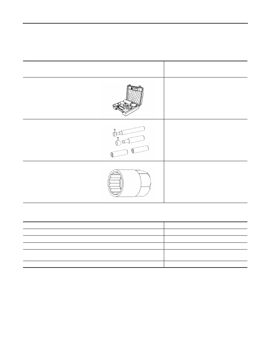
PREPARATION
Special Service Tools
INFOID:0000000010428769
Commercial Service Tools
INFOID:0000000010428770
Tool number
Renault tool number
Tool name
Description
KV32910340
Bvi.1683
Gearbox repair kit
Tool kit for repairing RS6F95R gearbox
Bvi.1902
Gearbox renovation kit
Gearbox renovation kit
Use in addition to KV32910340 (Bvi. 1683)
Bvi.1934
Reverse gear switch socket
Tool for installing gear switch
E1DIA0334ZZ
E1DIA0336ZZ
E1DIA0335ZZ
Tool name
Description
Roll pin punch
Removing differential bearing
Feeler gauge
Determine the thickness
Slide hammer 16 mm (0.63 in) dia.
Removing the control lever shaft
Slide hammer 14 mm (0.55 in) dia.
Removing the fork shaft bearing and selector
lever shaft ring
Separator
Removing differential bearings

GEAR OIL
TM-81
< PERIODIC MAINTENANCE >
[6MT: RS6F95R]
C
E
F
G
H
I
J
K
L
M
A
B
TM
N
O
P
PERIODIC MAINTENANCE
GEAR OIL
Exploded View
INFOID:0000000010428771
.
Draining
INFOID:0000000010428772
1.
Start engine and let it run to warm up transaxle.
2.
Stop engine. Remove drain plug (1) and then drain gear oil.
3.
Set a gasket on drain plug and install it to clutch housing.
Tighten drain plug to the specified torque.
CAUTION:
Never reuse gasket.
Refilling
INFOID:0000000010428773
1.
Remove filler plug (1). Fill with new gear oil until oil level reaches
the specified limit at filler plug hole as shown.
2.
After refilling gear oil, check oil level. Refer to
3.
Set a gasket on filler plug and then install it to transaxle case.
CAUTION:
Never reuse gasket.
4.
Tighten filler plug to the specified torque.
Inspection
INFOID:0000000010428774
LEAKAGE
Make sure that gear oil is not leaking from transaxle or around it.
LEVEL
1.
Remove filler plug (1) and check oil level at filler plug hole as
shown.
CAUTION:
Never start engine while checking oil level.
2.
Set a gasket on filler plug and then install it to transaxle case.
CAUTION:
Never reuse gasket.
3.
Tighten filler plug to the specified torque.
SCIA7622E
Oil grade and viscosity
: Refer to
.
Oil capacity
: Refer to
.
SCIA7623E
SCIA7623E
Нет комментариевНе стесняйтесь поделиться с нами вашим ценным мнением.
Текст