Qashqai J11. Transaxle & Transmission — part 4

TM-50
< UNIT DISASSEMBLY AND ASSEMBLY >
[6MT: RS6F94R]
TRANSAXLE ASSEMBLY
5.
Install oil channel and mainshaft front bearing outer race into
clutch housing using the drift (A) [SST: KV38100200].
CAUTION:
• Never reuse oil channel.
• Replace mainshaft front bearing outer race and mainshaft
front bearing inner race as a set.
6.
Install input shaft oil seal (1) into clutch housing using the drift
(A) [SST: ST33220000].
7.
Install snap ring (1) and oil channel (2) onto transaxle case.
8.
Install bearing preloading shim and mainshaft rear bearing outer
race into transaxle case using the drift (A) [SST: KV38100200].
CAUTION:
Replace mainshaft rear bearing outer race and mainshaft
rear bearing inner race as a set.
9.
Install bushings (1) into transaxle case using the drift (A) [Com-
mercial service tool].
PCIB1724E
PCIB1721E
PCIB1729E
PCIB1728E
JPDIC0109ZZ

TRANSAXLE ASSEMBLY
TM-51
< UNIT DISASSEMBLY AND ASSEMBLY >
[6MT: RS6F94R]
C
E
F
G
H
I
J
K
L
M
A
B
TM
N
O
P
10. Install oil gutter (1) onto transaxle case.
11. Install shifter lever oil seal (1) into transaxle case using the drift
(A) [Commercial service tool].
12. Install selector lever oil seal and bushings into transaxle case
using the drift [Commercial service tool].
13. Install shift finger (1) into transaxle case.
14. Install selector lever (1) and then install retaining pin.
CAUTION:
Never reuse retaining pin.
15. Install shim and differential side bearing outer race (transaxle
case side) into transaxle case using the drift (A) [SST:
ST33400001].
CAUTION:
Replace differential side bearing inner race and differential
side bearing outer race as a set.
PCIB1730E
JPDIC0102ZZ
PCIB1712E
BCIA0047E
PCIB1726E

TM-52
< UNIT DISASSEMBLY AND ASSEMBLY >
[6MT: RS6F94R]
TRANSAXLE ASSEMBLY
16. Install differential side bearing outer race (clutch housing side)
into clutch housing using the drift (A) [SST: KV38100200].
CAUTION:
Replace differential side bearing inner race and differential
side bearing outer race as a set.
17. Install differential side oil seals (1) into clutch housing and tran-
saxle case using the drift (A) [SST: KV38100300].
18. Install magnet onto clutch housing.
19. Install final drive assembly into clutch housing.
20. Install input shaft assembly (1), mainshaft assembly (2) and 1st-
2nd fork rod (3) into clutch housing.
21. Install spring washer located under the reverse idler shaft.
22. Install reverse gear assembly (1) according to the following.
a.
Lift up the input shaft assembly (2) and mainshaft assembly (3).
b.
Install reverse gear assembly and reverse fork rod (4) to clutch
housing.
23. Install 3rd-4th shift fork and 5th-6th shift fork to 3rd-4th and 5th-
6th fork rod.
PCIB1722E
B
: Transaxle case side
C
: Clutch housing side
Dimension “L
1
”
: 1.2 - 1.8 mm (0.047 - 0.071 in)
Dimension “L
2
”
: 2.7 - 3.3 mm (0.106 - 0.130 in)
JPDIC0120ZZ
PCIB1702E
PCIB1701E

TRANSAXLE ASSEMBLY
TM-53
< UNIT DISASSEMBLY AND ASSEMBLY >
[6MT: RS6F94R]
C
E
F
G
H
I
J
K
L
M
A
B
TM
N
O
P
24. While lifting up fork rod (1), install 3rd-4th and 5th-6th fork rod
assembly to clutch housing.
CAUTION:
Replace the 5th-6th shift fork, the 3rd-4th shift fork, and the
3rd-4th and 5th-6th fork rod as a set.
25. Install retaining pin into 5th-6th shift fork using a pin punch.
CAUTION:
Never reuse retaining pin.
26. Move 1st-2nd fork rod (1), 3rd-4th and 5th-6th fork rod assembly
(2), and reverse fork rod (3) to neutral position.
27. Install selector (4) into clutch housing.
28. Install spring of selector into return bushing.
29. Apply recommended sealant onto the mating surface of tran-
saxle case.
• Use Genuine Liquid Gasket, Three Bond 1215 or an equiv-
alent.
CAUTION:
• Remove old sealant adhering to the mating surfaces. Also
remove any moisture, oil, or foreign material adhering to
both mating surfaces.
• Check for damage on the mating surface.
• Apply a continuous bead of liquid gasket to the mating surface.
30. Engage shift finger and selector by moving selector lever (1).
Install transaxle case to clutch housing.
PCIB1700E
PCIB1699E
SCIA7782E
JPDIC0110ZZ

TM-54
< UNIT DISASSEMBLY AND ASSEMBLY >
[6MT: RS6F94R]
TRANSAXLE ASSEMBLY
31. Install seal washer and reverse idler shaft mounting bolt, and
then tighten mounting bolt to the specified torque.
CAUTION:
Never reuse seal washer.
32. Tighten mounting bolts to the specified torque.
33. Apply recommended sealant to threads of position switch (1).
Then install it to transaxle case and tighten to the specified
torque.
• Use Genuine Liquid Gasket, Three Bond 1215 or an equiv-
alent.
34. Install bracket (2), and then mounting bolt to the specified
torque.
35. Install shifter lever (3), and then install retaining pin using a pin
punch.
CAUTION:
Never reuse retaining pin.
36. Install gasket onto drain plug, and then install it into clutch hous-
ing using the socket [Commercial service tool]. Tighten drain plug to the specified torque.
CAUTION:
Never reuse gasket.
37. Install gasket onto filler plug, and then install it into transaxle case. Tighten filler plug to the specified
torque.
CAUTION:
• Never reuse gasket.
• After gear oil is filled, tighten filler plug to specified torque.
PCIB1695E
PCIB1694E
SCIA7784E
INPUT SHAFT AND GEAR
TM-55
< UNIT DISASSEMBLY AND ASSEMBLY >
[6MT: RS6F94R]
C
E
F
G
H
I
J
K
L
M
A
B
TM
N
O
P
INPUT SHAFT AND GEAR
Exploded View
INFOID:0000000010288460
.
Disassembly
INFOID:0000000010288461
CAUTION:
• Set input shaft on the vise with back plate and remove gears and snap rings.
• For installation and removal of snap ring, set snap ring pliers
and flat pliers at both sides of snap ring. Stretch snap ring,
and move it with flat pliers.
• Disassemble gear components putting matching marks on
the parts that do not affect any functions.
1.
Remove input shaft rear bearing mounting bolt (1), using the
drift (A) [SST: KV32300QAM].
2.
Set the drift (A) [Commercial service tool] and puller to input
shaft rear bearing (1), and remove input shaft rear bearing from
input shaft using a press.
3.
Remove washer (1), 6th input gear (2) and 5th-6th synchronizer
assembly (3).
4.
Remove needle bearing.
SCIA1755J
JPDIC0449ZZ
JPDIC0111ZZ
PCIB1750E

TM-56
< UNIT DISASSEMBLY AND ASSEMBLY >
[6MT: RS6F94R]
INPUT SHAFT AND GEAR
5.
Remove snap ring (1), washer and 5th input gear (2).
6.
Remove washer.
7.
Remove snap ring (1), washer, 4th input gear (2) and 3rd-4th
synchronizer assembly (3).
8.
Remove snap ring (1), washer and 3rd input gear (2).
9.
Remove input shaft front bearing (1) from input shaft using a
press.
Assembly
INFOID:0000000010288462
Note the following, and assembly is in the reverse order of disassembly.
PCIB1754E
PCIB1753E
PCIB1752E
PCIB1751E

INPUT SHAFT AND GEAR
TM-57
< UNIT DISASSEMBLY AND ASSEMBLY >
[6MT: RS6F94R]
C
E
F
G
H
I
J
K
L
M
A
B
TM
N
O
P
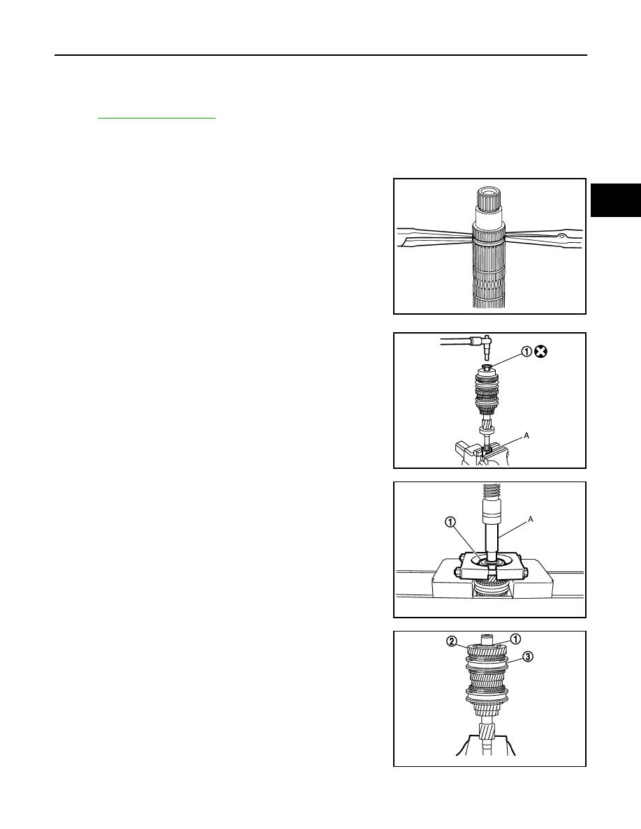
• Press-fit the input shaft front bearing (1) onto the input shaft using
the drift (A) [Commercial service tool] and press.
• Press-fit the input shaft rear bearing (1) onto the input shaft using
the drift (A) [Commercial service tool], the drift (B) [SST:
ST36720030] and press.
CAUTION:
• Never reuse snap ring.
• Make sure that snap ring is securely installed in the groove.
• Apply gear oil to baulk ring.
• Replace coupling sleeve and synchronizer hub as a set.
• Be careful with the orientation of 3rd-4th synchronizer hub.
• Be careful with the orientation of 5th-6th synchronizer hub.
• Install input shaft rear bearing mountinb bolt according to the following procedure.
CAUTION:
Follow the procedure. Otherwise, it may cause transaxle malfunction.
JPDIC0112ZZ
JPDIC0113ZZ
A
: 3rd input gear side
B
: 4th input gear side
PCIB1748E
A
: 5th input gear side
B
: 6th input gear side
PCIB1749E

TM-58
< UNIT DISASSEMBLY AND ASSEMBLY >
[6MT: RS6F94R]
INPUT SHAFT AND GEAR
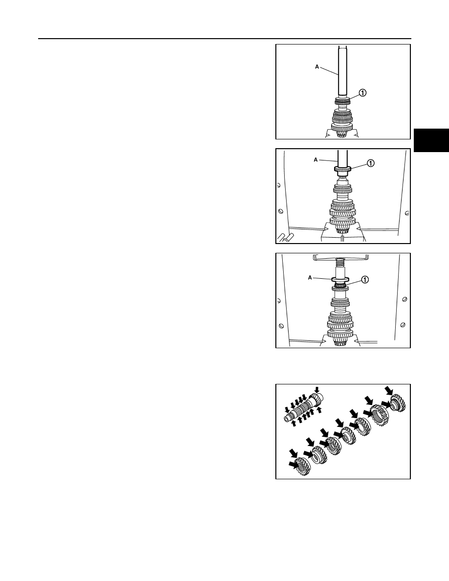
1.
Install the drift (A) [SST: KV32300QAM] in a vise.
2.
Install input shaft assembly in the drift (A) [SST: KV32300QAM].
3.
Install input shaft rear bearing mounting bolt (1). Tighten input
shaft rear bearing mounting bolt to the specified torque.
4.
Loosen input shaft rear bearing mounting bolt by a half turn.
5.
Tighten input shaft rear bearing mounting bolt to the specified
torque.
Inspection
INFOID:0000000010288463
INPUT SHAFT AND GEAR
Check items below. If necessary, replace them with new ones.
• Damage, peeling, dent, uneven wear, bending, and other non-
standard conditions of the shaft.
• Excessive wear, damage, peeling, and other non-standard condi-
tions of the gears.
SYNCHRONIZER
Synchronizer Hub and Coupling Sleeve
Check items below. If necessary, replace them with new ones.
• Damage and excessive wear of contact surfaces of coupling
sleeve, synchronizer hub and insert key.
• Coupling sleeve and synchronizer hub must move smoothly.
Baulk Ring
Check items below. If necessary, replace them with new ones.
• If any crack, damage, or excessive wear is found on cam face of
baulk ring or working face of insert, replace it.
BEARING
Tightening torque
100 N·m (10 kg-m, 74 ft-lb)
Tightening torque
165 N·m (17 kg-m, 122 ft-lb)
JPDIC0449ZZ
SCIA7736E
SCIA1753J
SCIA0608J

INPUT SHAFT AND GEAR
TM-59
< UNIT DISASSEMBLY AND ASSEMBLY >
[6MT: RS6F94R]
C
E
F
G
H
I
J
K
L
M
A
B
TM
N
O
P
Check items below. If necessary, replace them with new ones.
• Damage and rough rotation of bearing
MTF0041D

TM-60
< UNIT DISASSEMBLY AND ASSEMBLY >
[6MT: RS6F94R]
MAINSHAFT AND GEAR
MAINSHAFT AND GEAR
Exploded View
INFOID:0000000010288464
.
Disassembly
INFOID:0000000010288465
CAUTION:
• Set mainshaft on the vise with back plate and remove gears and snap rings.
• For installation and removal of snap ring, set snap ring pliers
and flat pliers at both sides of snap ring. Stretch snap ring,
and move it with flat pliers.
• Disassemble gear components putting matching marks on
the parts that do not affect any functions.
1.
Remove snap ring (1).
2.
Set the drift (A) [SST: ST33052000] and puller on 6th main gear
(1), and remove mainshaft rear bearing inner race (2) and 6th
main gear from mainshaft using a press.
3.
Set the drift (A) [SST: ST33052000] and puller on 4th main gear
(1), and remove 5th main gear (2), and 4th main gear from main-
shaft using a press.
4.
Remove intermediate adjusting shim.
SCIA1755J
PCIB1745E
PCIB1744E
PCIB1743E

MAINSHAFT AND GEAR
TM-61
< UNIT DISASSEMBLY AND ASSEMBLY >
[6MT: RS6F94R]
C
E
F
G
H
I
J
K
L
M
A
B
TM
N
O
P
5.
Set the drift (A) [SST: ST33052000] and puller on 1st main gear
(1), and remove 1st main gear, 1st-2nd synchronizer assembly
(2), 2nd main gear (3), bushing, and 3rd main gear (4) from
mainshaft using a press.
6.
Set the drift (A) [SST: ST33052000] and puller on mainshaft
front bearing inner race (1), and remove mainshaft front bearing
inner race from mainshaft using a press.
Assembly
INFOID:0000000010288466
CAUTION:
For installation and removal of snap ring, set snap ring pliers
and flat pliers at both sides of snap ring. Stretch snap ring, and
move it with flat pliers.
1.
Press-fit the mainshaft front bearing inner race (1) onto the
mainshaft using the drift (A) [SST: ST36720030] and press.
CAUTION:
Replace mainshaft front bearing outer race and mainshaft
front bearing inner race as a set.
2.
Apply gear oil to 1st inner baulk ring, 1st synchronizer cone, 1st
outer baulk ring, 2nd inner baulk ring, 2nd synchronizer cone,
and 2nd outer baulk ring.
PCIB1742E
PCIB1741E
SCIA1755J
PCIB1733E

TM-62
< UNIT DISASSEMBLY AND ASSEMBLY >
[6MT: RS6F94R]
MAINSHAFT AND GEAR
3.
Install 1st main gear (1), and 1st-2nd synchronizer assembly (2)
onto the mainshaft.
CAUTION:
• Replace 1st inner baulk ring, 1st synchronizer cone and
1st outer baulk ring as a set.
• Replace 2nd inner baulk ring, 2nd synchronizer cone and
2nd outer baulk ring as a set.
• Replace 1st-2nd coupling sleeve and 1st-2nd synchro-
nizer hub as a set.
4.
Press-fit the bushing (3) onto the mainshaft using the drift (A)
[SST: KV32102700] and press.
5.
Press-fit 3rd main gear (1) to the mainshaft using the drift (A)
[SST: KV32102700] and press after installing the 2nd main gear
(2) and the 3rd main gear to the mainshaft.
6.
Select the thickness of the intermediate adjusting shim (1)
needed by measuring the distance “L” between the base of the
mainshaft (2) and the top of the 3rd main gear (3).
Unit: mm (in)
7.
Install selected intermediate adjusting shim.
8.
Press-fit the 4th main gear (1) onto the mainshaft using the drift
(A) [SST: KV32102700].
PCIB1734E
PCIB1735E
Distance “L”
Adjusting shim thickness
147.690 – 147.666 (5.8146 – 5.8136)
1.500 (0.0591)
147.665 – 147.641 (5.8136 – 5.8126)
1.525 (0.0600)
147.640 – 147.616 (5.8126 – 5.8116)
1.550 (0.0610)
147.615 – 147.591 (5.8116 – 5.8107)
1.575 (0.0620)
147.590 – 147.566 (5.8106 – 5.8097)
1.600 (0.0630)
147.565 – 147.541 (5.8096 – 5.8087)
1.625 (0.0640)
147.540 – 147.516 (5.8086 – 5.8077)
1.650 (0.0650)
147.515 – 147.491 (5.8077 – 5.8067)
1.675 (0.0659)
147.490 – 147.466 (5.8067 – 5.8057)
1.700 (0.0669)
147.465 – 147.441 (5.8057 – 5.8048)
1.725 (0.0679)
147.440 – 147.416 (5.8047 – 5.8038)
1.750 (0.0689)
147.415 – 147.391 (5.8037 – 5.8028)
1.775 (0.0699)
PCIB1736E
PCIB1737E
MAINSHAFT AND GEAR
TM-63
< UNIT DISASSEMBLY AND ASSEMBLY >
[6MT: RS6F94R]
C
E
F
G
H
I
J
K
L
M
A
B
TM
N
O
P
9.
Press-fit the 5th main gear (1) onto the mainshaft using the drift
(A) [SST: KV32102700].
10. Press-fit the 6th main gear (1) onto the mainshaft using the drift
(A) [SST: KV32102700].
11. Press-fit the mainshaft rear bearing inner race (1) onto the main-
shaft using the drift (A) [SST: ST30901000].
CAUTION:
Replace mainshaft rear bearing outer race and mainshaft
rear bearing inner race as a set.
12. Install snap ring onto mainshaft.
CAUTION:
Never reuse snap ring.
Inspection
INFOID:0000000010288467
MAINSHAFT AND GEAR
Check items below. If necessary, replace them with new ones.
• Damage, peeling, dent, uneven wear, bending, and other non-
standard conditions of the shaft.
• Excessive wear, damage, peeling, and other non-standard condi-
tions of the gears.
SYNCHRONIZER
Synchronizer Hub and Coupling Sleeve
PCIB1738E
PCIB1739E
PCIB1740E
PCIB1775E

TM-64
< UNIT DISASSEMBLY AND ASSEMBLY >
[6MT: RS6F94R]
MAINSHAFT AND GEAR
Check items below. If necessary, replace them with new ones.
• Damage and excessive wear of contact surfaces of coupling
sleeve, synchronizer hub, insert key.
• Coupling sleeve and synchronizer hub must move smoothly.
Baulk Ring
Check items below. If necessary, replace them with new ones.
• If any crack, damage, or excessive wear is found on cam face of
baulk ring or working face of insert, replace it.
BEARING
Check for bearing damage and rough rotation. If necessary, replace
with a new one.
CAUTION:
When replacing tapered roller bearing, replace outer and inner
races as a set.
CAUTION:
Bearing preloading shim: after the intermediate adjusting shim and/or the 6th main gear, 5th main
gear, and 4th main gear have been replaced, it is necessary to modify the bearing preloading setting
by changing the bearing preloading shim.
• Replacing the intermediate adjusting shim.
- Increase the size of the bearing preloading shim, if the replaced intermediate adjusting shim is thin-
ner than the shim used before.
- Decrease the size of the bearing preloading shim, if the replaced intermediate adjusting shim is
thicker than the shim used before.
• Replacing the 6th main gear, 5th main gear, and 4th main gear.
- Measure the thickness of the main gear used before and the new main gear.
- Increase the thickness of the bearing preloading shim, if the difference is smaller than 0.025 mm
(0.0010 in).
- Decrease the thickness of the bearing preloading shim, if the difference is greater than 0.025 mm
(0.0010 in).
SCIA1753J
SCIA0608J
SPD715

REVERSE IDLER SHAFT AND GEAR
TM-65
< UNIT DISASSEMBLY AND ASSEMBLY >
[6MT: RS6F94R]
C
E
F
G
H
I
J
K
L
M
A
B
TM
N
O
P
REVERSE IDLER SHAFT AND GEAR
Exploded View
INFOID:0000000010288468
.
Disassembly
INFOID:0000000010288469
1.
Remove reverse output gear (1).
2.
Remove snap ring (1).
3.
Remove reverse baulk ring (1) and return spring (2).
4.
Remove snap ring (1), lock washer (2), reverse input gear (3)
and washer.
PCIB1760E
PCIB1759E
PCIB1758E
PCIB1757E
Нет комментариевНе стесняйтесь поделиться с нами вашим ценным мнением.
Текст