Nissan Murano. Manual — part 1378
TM-54
< DTC/CIRCUIT DIAGNOSIS >
[CVT: RE0F09B]
P0710 TRANSMISSION FLUID TEMPERATURE SENSOR A
8.
Stop the vehicle.
9.
Check the first trip DTC.
With GST
1.
Turn ignition switch OFF and cool the engine.
2.
Start the engine and wait for at least 2 minutes.
3.
Drive the vehicle and maintain the following conditions for 17 minutes or more.
4.
Stop the vehicle.
5.
Check the first trip DTC.
Is “P0710” detected?
YES
>> Go to
NO
>> GO TO 3.
3.
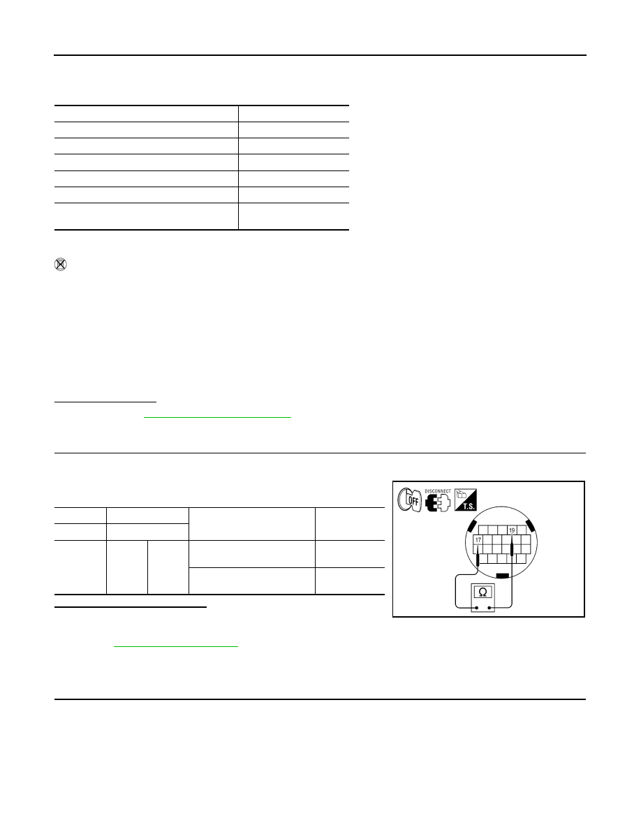
CHECK CVT FLUID TEMPERATURE SENSOR
1.
Turn ignition switch OFF.
2.
Disconnect CVT unit connector.
3.
Check resistance between CVT unit connector terminals.
Is the inspection result normal?
YES
>> INSPECTION END
NO
>> Replace the transaxle assembly due to malfunction in the CVT fluid temperature sensor. Refer to
Diagnosis Procedure
INFOID:0000000009719442
1.
CHECK CVT FLUID TEMPERATURE SENSOR CIRCUIT
1.
Turn ignition switch OFF.
2.
Disconnect TCM connector.
3.
Check resistance between TCM vehicle side harness connector terminals.
Accelerator pedal position
: 1.0/8 or more
Vehicle speed
: 10 km/h (7 MPH) or more
CVT fluid temperature before engine start
Driving time
−
40
°
C (
−
40
°
F) –
−
31
°
C (
−
23.8
°
F)
17 minutes or more
−
30
°
C (
−
22
°
F) –
−
21
°
C (
−
5.8
°
F)
15 minutes or more
−
20
°
C (
−
4
°
F) –
−
11
°
C (
−
12.2
°
F)
12 minutes or more
−
10
°
C (14
°
F) –
−
1
°
C (30.2
°
F)
9 minutes or more
0
°
C (32
°
F) – 9
°
C (48.2
°
F)
6 minutes or more
10
°
C (50
°
F) or more
—
(Go to 4.)
Selector lever
: “D” position
Accelerator pedal position
: 1.0/8 or more
Vehicle speed
: 10 km/h (7 MPH) or more
CVT unit
CVT unit
Condition
Resistance
(Approx.)
Connector
Terminal
F24
17
19
When CVT fluid temperature
is 20
°
C (68
°
F)
6.5 k
Ω
When CVT fluid temperature
is 80
°
C (176
°
F)
0.9 k
Ω
AWDIA0098ZZ
P0710 TRANSMISSION FLUID TEMPERATURE SENSOR A
TM-55
< DTC/CIRCUIT DIAGNOSIS >
[CVT: RE0F09B]
C
E
F
G
H
I
J
K
L
M
A
B
TM
N
O
P
Is the inspection result normal?
YES
>> GO TO 5.
NO
>> GO TO 2.
2.
CHECK HARNESS BETWEEN TCM AND CVT UNIT (CVT TEMPERATURE SENSOR) (PART 1)
1.
Disconnect CVT unit connector.
2.
Check continuity between TCM vehicle side harness connector terminals and CVT unit vehicle side har-
ness connector terminals.
Is the inspection result normal?
YES
>> GO TO 3.
NO
>> Repair or replace damaged parts.
3.
CHECK HARNESS BETWEEN TCM AND CVT UNIT (CVT TEMPERATURE SENSOR) (PART 2)
Check continuity between TCM vehicle side harness connector terminals and ground.
Is the inspection result normal?
YES
>> GO TO 4.
NO
>> Repair or replace damaged parts.
4.
CHECK CVT FLUID TEMPERATURE SENSOR
Check CVT fluid temperature sensor. Refer to
TM-55, "Component Inspection (CVT Fluid Temperature Sen-
Is the inspection result normal?
YES
>> GO TO 5.
NO
>> Replace transaxle assembly. Refer to
5.
DETECT MALFUNCTIONING ITEMS
Check TCM connector pin terminals for damage or loose connection with harness connector.
Is the inspection result normal?
YES
NO
>> Repair or replace damaged parts.
Component Inspection (CVT Fluid Temperature Sensor)
INFOID:0000000009719443
1.
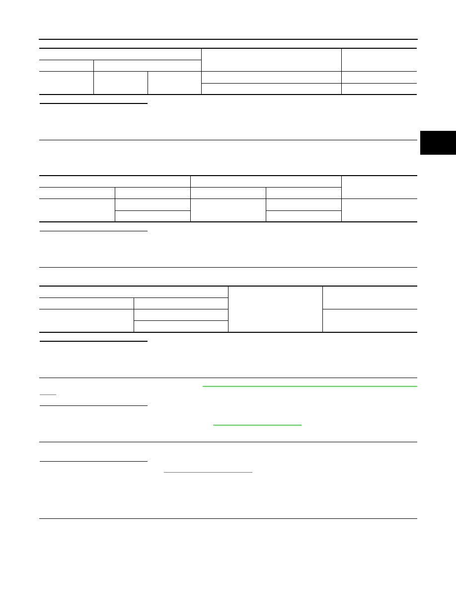
CHECK CVT FLUID TEMPERATURE SENSOR
Check resistance between CVT unit connector terminals.
TCM vehicle side harness connector
Condition
Resistance (Approx.)
Connector
Terminal
F23
13
25
When CVT fluid temperature is 20
°
C (68
°
F)
6.5 k
Ω
When CVT fluid temperature is 80
°
C (176
°
F)
0.9 k
Ω
TCM vehicle side harness connector
CVT unit vehicle side harness connector
Continuity
Connector
Terminal
Connector
Terminal
F23
13
F24
17
Existed
25
19
TCM vehicle side harness connector
Ground
Continuity
Connector
Terminal
F23
13
Not existed
25

TM-56
< DTC/CIRCUIT DIAGNOSIS >
[CVT: RE0F09B]
P0710 TRANSMISSION FLUID TEMPERATURE SENSOR A
Is the inspection result normal?
YES
>> INSPECTION END
NO
>> Replace transaxle assembly. Refer to
CVT unit connector
Condition
Resistance (Approx.)
Connector
Terminal
F24
17
19
When CVT fluid temperature is 20
°
C (68
°
F)
6.5 k
Ω
When CVT fluid temperature is 80
°
C (176
°
F)
0.9 k
Ω

P0715 INPUT SPEED SENSOR A
TM-57
< DTC/CIRCUIT DIAGNOSIS >
[CVT: RE0F09B]
C
E
F
G
H
I
J
K
L
M
A
B
TM
N
O
P
P0715 INPUT SPEED SENSOR A
Description
INFOID:0000000009719444
The primary speed sensor detects the primary pulley revolution speed and sends a signal to the TCM.
DTC Logic
INFOID:0000000009719445
DTC DETECTION LOGIC
DTC CONFIRMATION PROCEDURE
CAUTION:
Always drive vehicle at a safe speed.
NOTE:
Immediately after performing any “DTC CONFIRMATION PROCEDURE”, always turn ignition switch OFF.
Then wait at least 10 seconds before performing the next test.
1.
CHECK DTC DETECTION
With CONSULT
1.
Turn ignition switch ON.
2.
Select “Data Monitor” in “TRANSMISSION”.
3.
Start engine and maintain the following conditions for at least 5 consecutive seconds.
With GST
Follow the procedure “With CONSULT”.
Is “P0715” detected?
YES
>> Go to
NO
>> Check intermittent incident. Refer to
GI-44, "Intermittent Incident"
.
Diagnosis Procedure
INFOID:0000000009719446
1.
CHECK PRIMARY SPEED SENSOR
1.
Start engine.
2.
Check voltage between TCM connector terminals.
3.
If OK, check the pulse when vehicle drive.
DTC
Trouble diagnosis name
DTC is detected if...
Possible cause
P0715
Input/Turbine Speed Sensor
“A” Circuit
• Primary speed sensor signal is not input
due to an open circuit.
• An unexpected signal is input when vehi-
cle is being driven.
• Harness or connectors
(Sensor circuit is open or shorted.)
• Primary speed sensor
VEHICLE SPEED
: 10 km/h (6 MPH) or more
ACC PEDAL OPEN
: More than 1.0/8
RANGE
: “D” position
ENG SPEED
: 450 rpm or more
Driving location
: Driving the vehicle uphill (increased engine load) will help maintain the driving
conditions required for this test.
TCM connector
Voltage (Approx.)
Connector
Terminal
F23
25
26
4.75 – 5.25 V
TCM connector
Condition
Voltage (Approx.)
Connector
Terminal
F23
33
When driving [“L”position, 20 km/h (12 MPH)]
680 Hz
Нет комментариевНе стесняйтесь поделиться с нами вашим ценным мнением.
Текст