Nissan Murano. Manual — part 1377
TM-50
< DTC/CIRCUIT DIAGNOSIS >
[CVT: RE0F09B]
P0705 TRANSMISSION RANGE SENSOR A
P0705 TRANSMISSION RANGE SENSOR A
Description
INFOID:0000000009719436
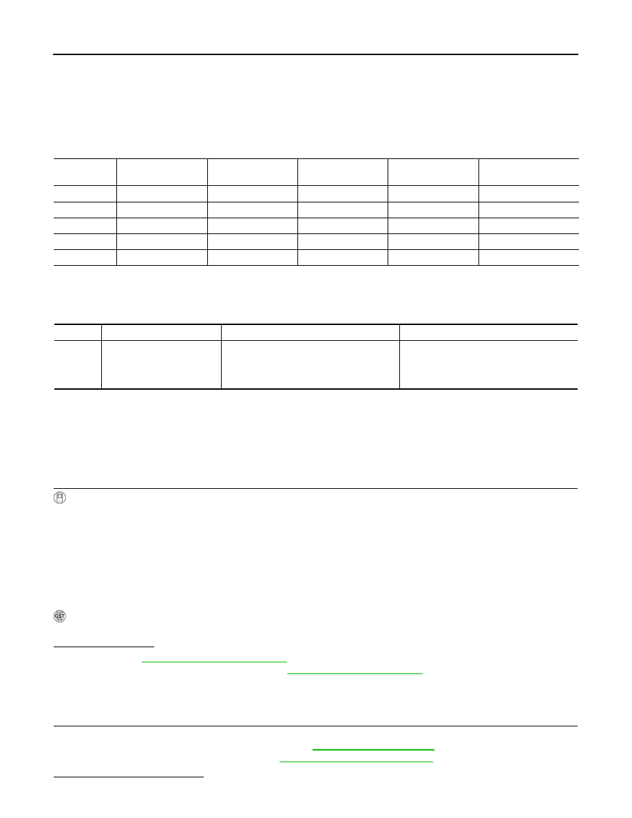
• The transmission range switch is included in the control valve assembly.
• The transmission range switch includes 4 transmission position switches.
• TCM judges the selector lever position by the transmission range switch signal.
DTC Logic
INFOID:0000000009719437
DTC DETECTION LOGIC
DTC CONFIRMATION PROCEDURE
CAUTION:
Always drive vehicle at a safe speed.
NOTE:
Immediately after performing any “DTC CONFIRMATION PROCEDURE”, always turn ignition switch OFF.
Then wait at least 10 seconds before performing the next test.
1.
CHECK DTC DETECTION
With CONSULT
1.
Turn ignition switch ON.
2.
Select “Data Monitor” in “TRANSMISSION”.
3.
Start engine.
4.
Drive vehicle and maintain the following conditions for at least 2 consecutive seconds.
With GST
Follow the procedure “With CONSULT”.
Is “P0705” detected?
YES
>> Go to
NO
>> Check intermittent incident. Refer to
GI-44, "Intermittent Incident"
.
Diagnosis Procedure
INFOID:0000000009719438
1.
CHECK CVT POSITION
1.
Disconnect CVT unit connector.
2.
Remove control cable from manual lever. Refer to
.
3.
Check transmission range switch. Refer to
Is the inspection result normal?
Shift position
Transmission range
switch 1
Transmission range
switch 2
Transmission range
switch 3
Transmission range
switch 4
Transmission range
switch 3 (monitor)
P
OFF
OFF
OFF
OFF
OFF
R
ON
OFF
OFF
ON
OFF
N
ON
ON
OFF
OFF
OFF
D
ON
ON
ON
ON
ON
L
OFF
ON
ON
OFF
ON
DTC
Trouble diagnosis name
DTC is detected if...
Possible cause
P0705
Transmission Range Sensor
“A” Circuit (PRNDL Input)
TCM does not receive the correct voltage
signal (based on the gear position) from the
switch.
• Harness or connectors
(Transmission range switches circuit is
open or shorted.)
• Transmission range switch
VEHICLE SPEED
: More than 10 km/h (6 MPH)
ENG SPEED SIG
: More than 450 rpm
ACC PEDAL OPEN
: More than 1.0/8
P0705 TRANSMISSION RANGE SENSOR A
TM-51
< DTC/CIRCUIT DIAGNOSIS >
[CVT: RE0F09B]
C
E
F
G
H
I
J
K
L
M
A
B
TM
N
O
P
YES
>> Adjust CVT position. Refer to
TM-164, "Inspection and Adjustment"
NO
>> GO TO 2.
2.
CHECK HARNESS BETWEEN TCM AND TRANSMISSION RANGE SWITCH (PART 1)
1.
Turn ignition switch OFF.
2.
Disconnect TCM connector.
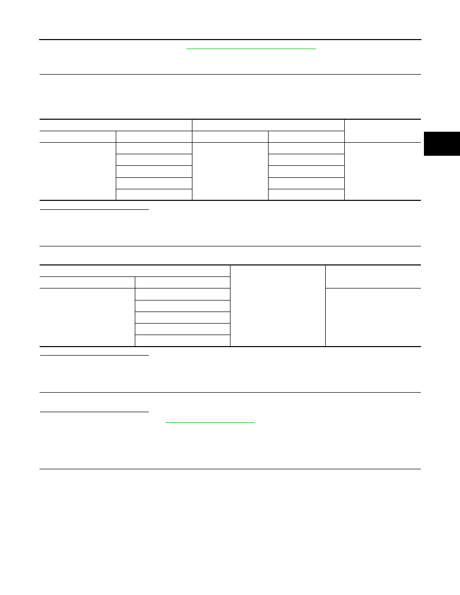
3.
Check continuity between TCM vehicle side harness connector terminals and CVT unit vehicle side har-
ness connector terminals.
Is the inspection result normal?
YES
>> GO TO 3.
NO
>> Repair or replace damaged parts.
3.
CHECK HARNESS BETWEEN TCM AND TRANSMISSION RANGE SWITCH (PART 2)
Check continuity between TCM vehicle side harness connector terminals and ground.
Is the inspection result normal?
YES
>> GO TO 4.
NO
>> Repair or replace damaged parts.
4.
DETECT MALFUNCTIONING ITEMS
Check TCM connector pin terminals for damage or loose connection with harness connector.
Is the inspection result normal?
YES
NO
>> Repair or replace damaged parts.
Component Inspection
INFOID:0000000009719439
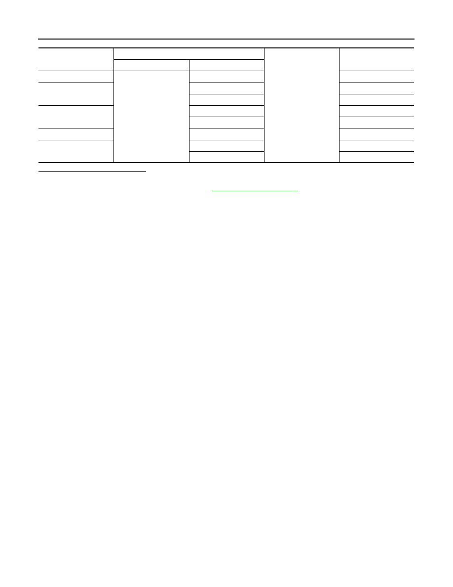
1.
CHECK TRANSMISSION RANGE SWITCH
Check the continuity of the transmission range switch by changing selector lever to various positions and
checking continuity between CVT unit terminals and ground.
TCM vehicle side harness connector
CVT unit vehicle side harness connector
Continuity
Connector
Terminal
Connector
Terminal
F23
1
F24
5
Existed
2
14
3
15
4
18
11
4
TCM vehicle side harness connector
Ground
Continuity
Connector Terminal
F23
1
Not existed
2
3
4
11
TM-52
< DTC/CIRCUIT DIAGNOSIS >
[CVT: RE0F09B]
P0705 TRANSMISSION RANGE SENSOR A
Is the inspection result normal?
YES
>> INSPECTION END
NO
>> Replace transaxle assembly. Refer to
Shift position
CVT unit connector
Ground
Continuity
Connector
Terminal
P
F24
4, 5, 14, 15, 18
Not existed
R
4, 15
Existed
5, 14, 18
Not existed
N
4, 5
Existed
14, 15, 18
Not existed
D
4, 5, 14, 15, 18
Existed
L
5, 14, 18
Existed
4, 15
Not existed
P0710 TRANSMISSION FLUID TEMPERATURE SENSOR A
TM-53
< DTC/CIRCUIT DIAGNOSIS >
[CVT: RE0F09B]
C
E
F
G
H
I
J
K
L
M
A
B
TM
N
O
P
P0710 TRANSMISSION FLUID TEMPERATURE SENSOR A
Description
INFOID:0000000009719440
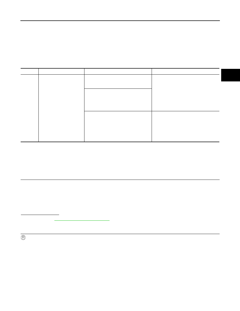
The CVT fluid temperature sensor detects the CVT fluid temperature and sends a signal to the TCM.
DTC Logic
INFOID:0000000009719441
DTC DETECTION LOGIC
DTC CONFIRMATION PROCEDURE
CAUTION:
Always drive vehicle at a safe speed.
NOTE:
Immediately after performing any “DTC CONFIRMATION PROCEDURE”, always turn ignition switch OFF.
Then wait at least 10 seconds before performing the next test.
1.
CHECK DTC DETECTION (PART 1)
1.
Start the engine.
2.
Maintain the following condition for 5 seconds or more.
3.
Stop the vehicle.
4.
Check the first trip DTC.
Is “P0710” detected?
YES
>> Go to
NO
>> GO TO 2.
2.
CHECK DTC DETECTION (PART 2)
With CONSULT
1.
Turn ignition switch OFF and cool the engine.
2.
Turn ignition switch ON.
CAUTION:
Never start the engine.
3.
Select “Data Monitor” in “TRANSMISSION”.
4.
Select “FLUID TEMP”.
5.
Record CVT fluid temperature.
6.
Start the engine and wait for at least 2 minutes.
7.
Drive the vehicle for the total minutes specified in the Driving time column below with the following condi-
tions satisfied.
DTC
Trouble diagnosis name
DTC is detected if...
Possible cause
P0710
Transmission Fluid Tempera-
ture Sensor “A” Circuit
During running, the CVT fluid temperature
sensor signal voltage is excessively high or
low.
• Harness or connectors
(Sensor circuit is open or shorted.)
• CVT fluid temperature sensor
CVT fluid temperature does not rise to 10
°
C
(50
°
F) after driving for a certain period of
time with the TCM-received fluid tempera-
ture sensor value between
−
40
°
C (
−
40
°
F)
and 9
°
C (48.2
°
F).
The following conditions are maintained for
5 minutes after the completion of engine di-
agnosis P0111, P0116, and P0196:
• A/T fluid temperature
−
Engine coolant
temperature > 55
°
C (131
°
F)
• A/T fluid temperature
−
Engine coolant
temperature <
−
27
°
C (
−
16.6
°
F)
A/T fluid temperature sensor
Vehicle speed
: 20 km/h (12 MPH) or more
Selector lever
: “D” position
Нет комментариевНе стесняйтесь поделиться с нами вашим ценным мнением.
Текст