Nissan Murano. Manual — part 819
HAC-50
< DTC/CIRCUIT DIAGNOSIS >
[WITHOUT 7 INCH DISPLAY]
B2578, B2579 IN-VEHICLE SENSOR
NOTE:
If DTC is displayed along with DTC U1000 or U1010, first diagnose the DTC U1000 or U1010. Refer to
.
DTC CONFIRMATION PROCEDURE
1.
CHECK WITH SELF-DIAGNOSIS FUNCTION OF CONSULT
1.
Using CONSULT, perform “SELF-DIAGNOSIS RESULTS” of HVAC.
2.
Check if any DTC No. is displayed in the self-diagnosis results.
NOTE:
If DTC is displayed along with DTC U1000 or U1010, first diagnose the DTC U1000 or U1010. Refer to
.
Is DTC No.“B2578” or “B2579” displayed?
YES
>> Perform trouble diagnosis for the in-vehicle sensor. Refer to
NO
>> INSPECTION END
Diagnosis Procedure
INFOID:0000000009722063
1.
CHECK VOLTAGE BETWEEN IN-VEHICLE SENSOR AND GROUND
1.
Disconnect in-vehicle sensor connector.
2.
Turn ignition switch ON.
3.
Check voltage between in-vehicle sensor harness connector and ground.
Is the inspection result normal?
YES
>> GO TO 2.
NO
>> GO TO 4.
2.
CHECK CIRCUIT CONTINUITY BETWEEN IN-VEHICLE SENSOR AND A/C AUTO AMP.
1.
Turn ignition switch OFF.
2.
Disconnect A/C auto amp. connector.
3.
Check continuity between in-vehicle sensor harness connector and A/C auto amp. harness connector.
Is the inspection result normal?
YES
>> GO TO 3.
NO
>> Repair harness or connector.
3.
CHECK IN-VEHICLE SENSOR
Check in-vehicle sensor. Refer to
HAC-51, "Component Inspection"
Is the inspection result normal?
YES
>> Replace A/C auto amp.
DTC
Items
(CONSULT screen terms)
Diagnostic item is detected when...
Possible cause
B2578
IN-VEHICLE SENSOR
Detected temperature at in-vehicle
sensor
−
44
°
C (
−
47
°
F) or less
• In-vehicle sensor
• A/C auto amp.
• Harness and connector
(In-vehicle sensor circuit is open,
or there is a short in the circuit)
B2579
Detected temperature at in-vehicle
sensor 100
°
C (212
°
F) or more
(+)
(
−
)
Voltage
In-vehicle sensor
—
Connector
Terminal
M41
1
Ground
Approx. 5 V
In-vehicle sensor
A/C auto amp.
Continuity
Connector
Terminal
Connector
Terminal
M41
2
M50
37
Existed
B2578, B2579 IN-VEHICLE SENSOR
HAC-51
< DTC/CIRCUIT DIAGNOSIS >
[WITHOUT 7 INCH DISPLAY]
C
D
E
F
G
H
J
K
L
M
A
B
HAC
N
O
P
NO
>> Replace in-vehicle sensor.
4.
CHECK CIRCUIT CONTINUITY BETWEEN IN-VEHICLE SENSOR AND A/C AUTO AMP.
1.
Turn ignition switch OFF.
2.
Disconnect A/C auto amp. connector.
3.
Check continuity between in-vehicle sensor harness connector and A/C auto amp. harness connector.
4.
Check continuity between in-vehicle sensor harness connector and ground.
Is the inspection result normal?
YES
>> Replace A/C auto amp.
NO
>> Repair harness or connector.
Component Inspection
INFOID:0000000009722064
1.
CHECK IN-VEHICLE SENSOR
1.
Turn ignition switch OFF.
2.
Disconnect in-vehicle sensor connector. Refer to
.
3.
Check resistance between in-vehicle sensor terminals.
Is the inspection result normal?
YES
>> INSPECTION END
NO
>> Replace in-vehicle sensor.
In-vehicle sensor
A/C auto amp.
Continuity
Connector
Terminal
Connector
Terminal
M41
1
M50
36
Existed
In-vehicle sensor
—
Continuity
Connector
Terminal
M41
1
Ground
Not existed
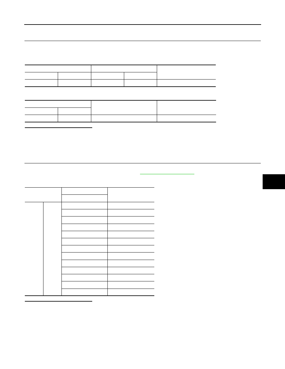
Terminal
Condition
Resistance k
Ω
Temperature
°
C (
°
F)
1
2
−
15 (5)
12.73
−
10 (14)
9.92
−
5 (23)
7.80
0 (32)
6.19
5 (41)
4.95
10 (50)
3.99
15 (59)
3.24
20 (68)
2.65
25 (77)
2.19
30 (86)
1.81
35 (95)
1.51
40 (104)
1.27
45 (113)
1.07
HAC-52
< DTC/CIRCUIT DIAGNOSIS >
[WITHOUT 7 INCH DISPLAY]
B2581, B2582 INTAKE SENSOR
B2581, B2582 INTAKE SENSOR
Description
INFOID:0000000009722065
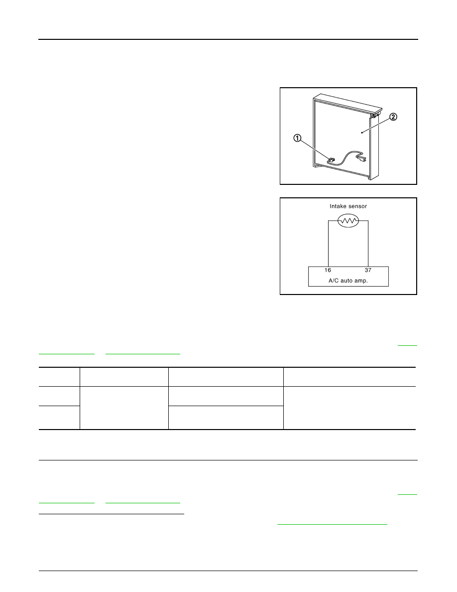
Intake Sensor
• The intake sensor (1) is located on the evaporator (2).
• It converts air temperature after it passes through the evaporator
into a resistance value which is then input to the A/C auto amp.
Intake Sensor Circuit
DTC Logic
INFOID:0000000009722066
DTC DETECTION LOGIC
NOTE:
If DTC is displayed along with DTC U1000 or U1010, first diagnose the DTC U1000 or U1010. Refer to
.
DTC CONFIRMATION PROCEDURE
1.
CHECK WITH SELF-DIAGNOSIS FUNCTION OF CONSULT
1.
Using CONSULT, perform “SELF-DIAGNOSIS RESULTS” of HVAC.
2.
Check if any DTC No. is displayed in the self-diagnosis results.
NOTE:
If DTC is displayed along with DTC U1000 or U1010, first diagnose the DTC U1000 or U1010. Refer to
.
Is DTC No.“B2581” or “B2582” displayed?
YES
>> Perform trouble diagnosis for the intake sensor. Refer to
.
NO
>> INSPECTION END
Diagnosis Procedure
INFOID:0000000009722067
1.
CHECK VOLTAGE BETWEEN INTAKE SENSOR AND GROUND
JPIIA1351ZZ
JPIIA0614GB
DTC
Items
(CONSULT screen terms)
Diagnostic item is detected when...
Possible cause
B2581
INTAKE SENSOR
Detected temperature at intake sensor
−
33
°
C (
−
27
°
F) or less
• Intake sensor
• A/C auto amp.
• Harness and connector
(Intake sensor circuit is open, or there is a
short in the circuit)
B2582
Detected temperature at intake sensor
69
°
C (156
°
F) or more
B2581, B2582 INTAKE SENSOR
HAC-53
< DTC/CIRCUIT DIAGNOSIS >
[WITHOUT 7 INCH DISPLAY]
C
D
E
F
G
H
J
K
L
M
A
B
HAC
N
O
P
1.
Disconnect intake sensor connector.
2.
Turn ignition switch ON.
3.
Check voltage between intake sensor harness connector and ground.
Is the inspection result normal?
YES
>> GO TO 2.
NO
>> GO TO 4.
2.
CHECK CIRCUIT CONTINUITY BETWEEN INTAKE SENSOR AND A/C AUTO AMP.
1.
Turn ignition switch OFF.
2.
Disconnect A/C auto amp. connector.
3.
Check continuity between intake sensor harness connector and A/C auto amp. harness connector.
Is the inspection result normal?
YES
>> GO TO 3.
NO
>> Repair harness or connector.
3.
CHECK INTAKE SENSOR
Check intake sensor. Refer to
HAC-53, "Component Inspection"
.
Is the inspection result normal?
YES
>> Replace A/C auto amp.
NO
>> Replace intake sensor.
4.
CHECK CIRCUIT CONTINUITY BETWEEN INTAKE SENSOR AND A/C AUTO AMP.
1.
Turn ignition switch OFF.
2.
Disconnect A/C auto amp. connector.
3.
Check continuity between intake sensor harness connector and A/C auto amp. harness connector.
4.
Check continuity between intake sensor harness connector and ground.
Is the inspection result normal?
YES
>> Replace A/C auto amp.
NO
>> Repair harness or connector.
Component Inspection
INFOID:0000000009722068
1.
CHECK INTAKE SENSOR
1.
Turn ignition switch OFF.
2.
Disconnect intake sensor connector.
3.
Check resistance between intake sensor terminals.
(+)
(
−
)
Voltage
Intake sensor
—
Connector
Terminal
M42
1
Ground
Approx. 5 V
Intake sensor
A/C auto amp.
Continuity
Connector
Terminal
Connector
Terminal
M42
2
M50
37
Existed
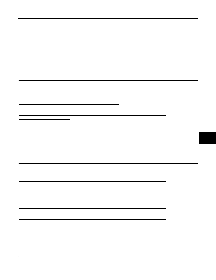
Intake sensor
A/C auto amp.
Continuity
Connector
Terminal
Connector
Terminal
M42
1
M50
16
Existed
Intake sensor
—
Continuity
Connector
Terminal
M42
1
Ground
Not existed
Нет комментариевНе стесняйтесь поделиться с нами вашим ценным мнением.
Текст