Nissan Murano. Manual — part 818
HAC-46
< DTC/CIRCUIT DIAGNOSIS >
[WITHOUT 7 INCH DISPLAY]
B257B, B257C AMBIENT SENSOR
B257B, B257C AMBIENT SENSOR
Description
INFOID:0000000009722057
COMPONENT DESCRIPTION
Ambient Sensor
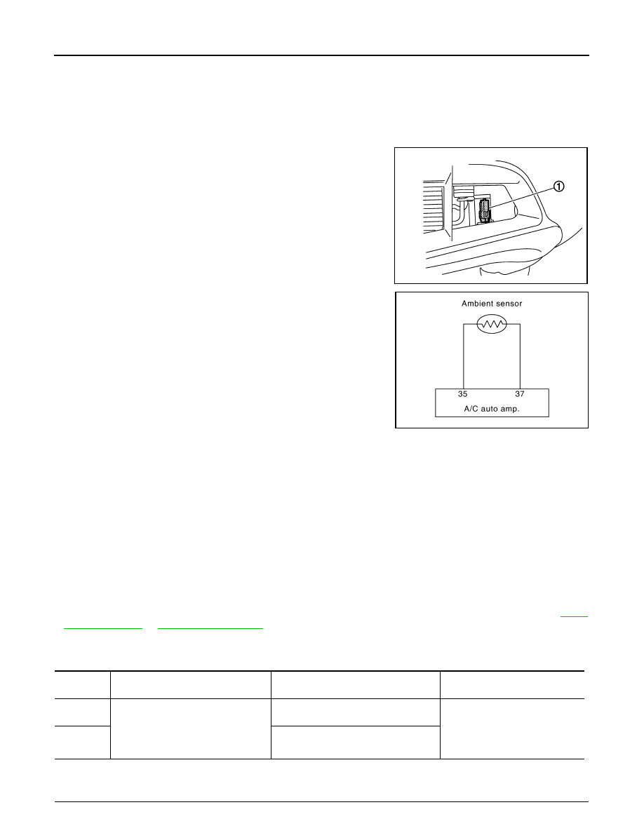
• The ambient sensor (1) is installed to the front bumper (left back).
• It detects ambient temperature and converts it into a resistance
value which is then input into the A/C auto amp.
Ambient Sensor Circuit
AMBIENT TEMPERATURE INPUT PROCESS
The A/C auto amp. equips a processing circuit for the ambient sensor input. However, when the temperature
detected by the ambient sensor increases quickly, the processing circuit retards the A/C auto amp. function. It
only allows the A/C auto amp. to recognize an ambient temperature increase of 0.33
°
C (0.6
°
F) per 100 sec-
onds.
As an example, consider stopping for a few minutes after high speed driving. Although the actual ambient tem-
perature has not changed, the temperature detected by the ambient sensor increases. This is because the
heat from the engine compartment can radiate to the front bumper area, the location of the ambient sensor.
DTC Logic
INFOID:0000000009722058
DTC DETECTION LOGIC
NOTE:
• If DTC is displayed along with DTC U1000 or U1010, first diagnose the DTC U1000 or U1010. Refer to
.
• If there is an open circuit in the ambient sensor, A/C auto amp. registers extreme cold [
−
44
°
C (
−
47
°
F)] and
adjusts the temperature control warmer.
DTC CONFIRMATION PROCEDURE
1.
CHECK WITH SELF-DIAGNOSIS FUNCTION OF CONSULT
JSIIA1532JP
JPIIA0612GB
DTC
Items
(CONSULT screen terms)
Diagnostic item is detected when...
Possible cause
B257B
AMBIENT SENSOR
Detected temperature at ambient sensor
−
44
°
C (
−
47
°
F) or less
• Ambient sensor
• A/C auto amp.
• Harness and connector
(Ambient sensor circuit is open,
or there is a short in the circuit)
B257C
Detected temperature at ambient sensor
100
°
C (212
°
F) or more

B257B, B257C AMBIENT SENSOR
HAC-47
< DTC/CIRCUIT DIAGNOSIS >
[WITHOUT 7 INCH DISPLAY]
C
D
E
F
G
H
J
K
L
M
A
B
HAC
N
O
P
1.
Using CONSULT, perform “SELF-DIAGNOSIS RESULTS” of HVAC.
2.
Check if any DTC No. is displayed in the self-diagnosis results.
NOTE:
• If DTC is displayed along with DTC U1000 or U1010, first diagnose the DTC U1000 or U1010. Refer to
.
• If there is an open circuit in the ambient sensor, A/C auto amp. registers extreme cold [
−
44
°
C (
−
47
°
F)] and
adjusts the temperature control warmer.
Is DTC No.“B257B” or “B257C” displayed?
YES
>> Perform trouble diagnosis for the ambient sensor. Refer to
.
NO
>> INSPECTION END
Diagnosis Procedure
INFOID:0000000009722059
1.
CHECK VOLTAGE BETWEEN AMBIENT SENSOR AND GROUND
1.
Disconnect ambient sensor connector.
2.
Turn ignition switch ON.
3.
Check voltage between ambient sensor harness connector and ground.
Is the inspection result normal?
YES
>> GO TO 2.
NO
>> GO TO 4.
2.
CHECK CIRCUIT CONTINUITY BETWEEN AMBIENT SENSOR AND A/C AUTO AMP.
1.
Turn ignition switch OFF.
2.
Disconnect A/C auto amp. connector.
3.
Check continuity between ambient sensor harness connector and A/C auto amp. harness connector.
Is the inspection result normal?
YES
>> GO TO 3.
NO
>> Repair harness or connector.
3.
CHECK AMBIENT SENSOR
Check ambient sensor. Refer to
HAC-48, "Component Inspection"
.
Is the inspection result normal?
YES
>> Replace A/C auto amp.
NO
>> Replace ambient sensor.
4.
CHECK CIRCUIT CONTINUITY BETWEEN AMBIENT SENSOR AND A/C AUTO AMP.
1.
Turn ignition switch OFF.
2.
Disconnect A/C auto amp. connector.
3.
Check continuity between ambient sensor harness connector and A/C auto amp. harness connector.
4.
Check continuity between ambient sensor harness connector and ground.
(+)
(
−
)
Voltage
Ambient sensor
—
Connector
Terminal
E337
1
Ground
Approx. 5 V
Ambient sensor
A/C auto amp.
Continuity
Connector
Terminal
Connector
Terminal
E337
2
M50
37
Existed
Ambient sensor
A/C auto amp.
Continuity
Connector
Terminal
Connector
Terminal
E337
1
M50
35
Existed

HAC-48
< DTC/CIRCUIT DIAGNOSIS >
[WITHOUT 7 INCH DISPLAY]
B257B, B257C AMBIENT SENSOR
Is the inspection result normal?
YES
>> Replace A/C auto amp.
NO
>> Repair harness or connector.
Component Inspection
INFOID:0000000009722060
1.
CHECK AMBIENT SENSOR
1.
Turn ignition switch OFF.
2.
Disconnect ambient sensor connector. Refer to
3.
Check resistance between ambient sensor terminals.
Is the inspection result normal?
YES
>> INSPECTION END
NO
>> Replace ambient sensor.
Ambient sensor
—
Continuity
Connector
Terminal
E337
1
Ground
Not existed
Terminal
Condition
Resistance k
Ω
Temperature
°
C (
°
F)
1
2
−
15 (5)
12.73
−
10 (14)
9.92
−
5 (23)
7.80
0 (32)
6.19
5 (41)
4.95
10 (50)
3.99
15 (59)
3.24
20 (68)
2.65
25 (77)
2.19
30 (86)
1.81
35 (95)
1.51
40 (104)
1.27
45 (113)
1.07
B2578, B2579 IN-VEHICLE SENSOR
HAC-49
< DTC/CIRCUIT DIAGNOSIS >
[WITHOUT 7 INCH DISPLAY]
C
D
E
F
G
H
J
K
L
M
A
B
HAC
N
O
P
B2578, B2579 IN-VEHICLE SENSOR
Description
INFOID:0000000009722061
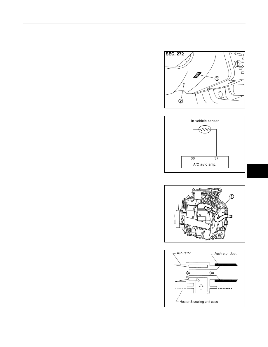
In-vehicle Sensor
• The in-vehicle sensor (1) is located on instrument driver lower
panel (2).
• It converts variations in compartment air temperature drawn from
the aspirator into a resistance value. It is then input into the A/C
auto amp.
In-vehicle Sensor Circuit
Aspirator
The aspirator (1) is located on driver side of heater & cooling unit
assembly. It produces vacuum pressure due to air discharged from
the heater & cooling unit assembly, continuously taking compartment
air in the aspirator.
DTC Logic
INFOID:0000000009722062
DTC DETECTION LOGIC
JPIIA0557ZZ
JPIIA0613GB
JPIIA0517ZZ
RJIA1804E
Нет комментариевНе стесняйтесь поделиться с нами вашим ценным мнением.
Текст