Nissan Murano. Manual — part 755
FRONT DRIVE SHAFT BOOT
FAX-15
< REMOVAL AND INSTALLATION >
[2WD]
C
E
F
G
H
I
J
K
L
M
A
B
FAX
N
O
P
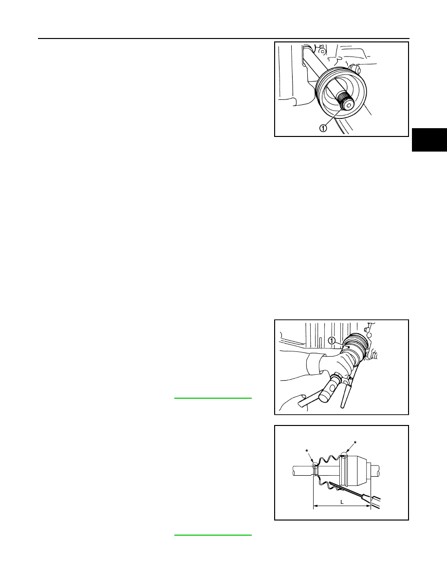
13. Remove circular clip (1) from housing assembly.
14. Remove boot from housing assembly.
INSTALLATION
1.
Clean the old grease on joint sub-assembly with paper waste.
2.
Fill serration slot joint sub-assembly with NISSAN genuine grease or equivalent until the serration slot and
ball groove become full to the brim.
CAUTION:
After applying grease, use a paper waste to wipe off old grease that has oozed out.
3.
Install boot and boot bands to housing assembly.
CAUTION:
• Wrap serration on housing assembly with tape to protect the boot from damage.
• Never reuse boot and boot band.
4.
Remove the tape wrapped around the serration on housing assembly.
5.
Position the circular clip on groove at the housing assembly edge.
CAUTION:
Never reuse circular clip.
NOTE:
Drive joint inserter is recommended when installing circular clip.
6.
Align both center axles of the housing assembly edge and joint sub-assembly. Then assemble housing
assembly with joint sub-assembly holding circular clip.
7.
Install joint sub-assembly (1) to housing assembly using plastic
hammer.
CAUTION:
Confirm that joint sub-assembly is correctly engaged while
rotating drive housing assembly.
8.
Apply the specified amount of grease into the boot inside from
large diameter side of boot.
9.
Install the boot securely into grooves (indicated by “*” marks)
shown in the figure.
CAUTION:
If grease adheres to the boot mounting surface (indicated
by “*” mark) on the housing assembly or joint sub-assem-
bly, boot may be removed. Remove all grease from the boot
mounting surface.
10. To prevent the deformation of the boot, adjust the boot installa-
tion length (L) to the specified value shown below by inserting
the suitable tool into inside of the boot from the large diameter
side of the boot and discharging the inside air.
CAUTION:
• If the boot installation length exceeds the standard, it may cause breakage of boot.
JPDIF0007ZZ
Grease amount
: Refer to
.
JPDIF0011ZZ
L
: Refer to
.
JPDIF0222ZZ
FAX-16
< REMOVAL AND INSTALLATION >
[2WD]
FRONT DRIVE SHAFT BOOT
• Be careful not to touch the inside of the boot with a tip of tool.
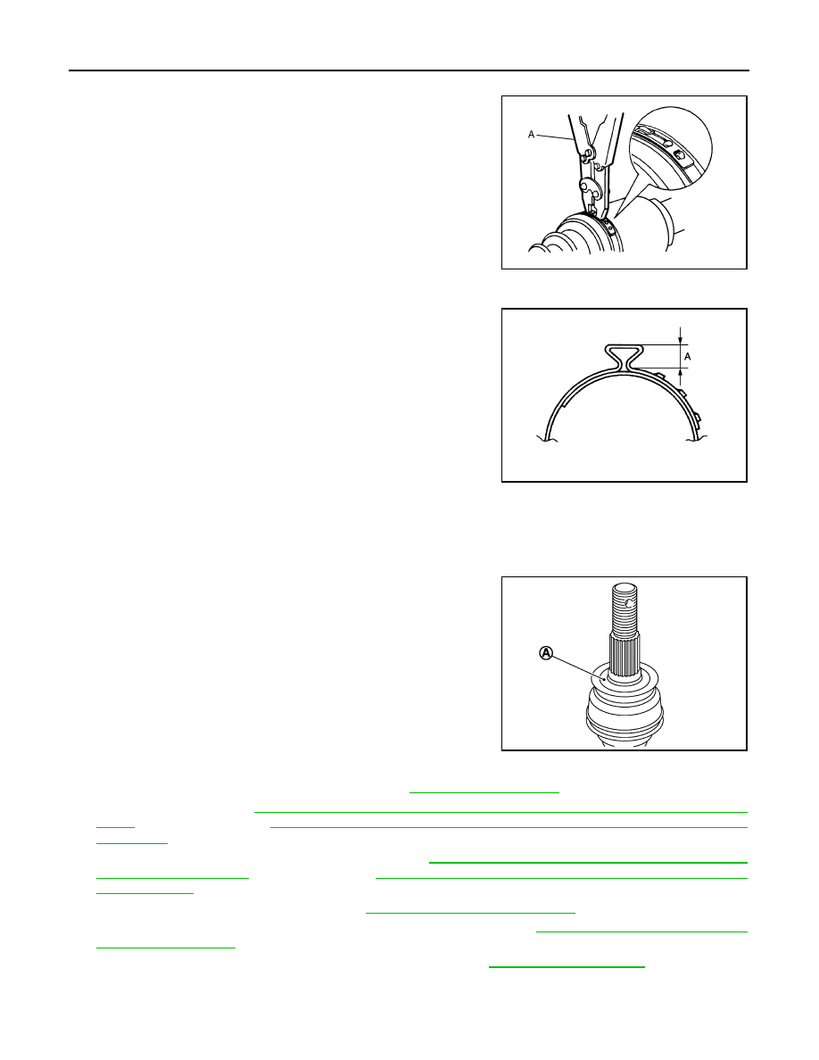
11. Secure the large and small ends of the boot with boot bands
using the boot band crimping tool (A) [SST: KV40107300 (
—
)].
CAUTION:
Never reuse boot band.
NOTE:
Secure boot band so that dimension (A) meets the specification
as shown in the figure.
12. Secure joint sub-assembly and housing assembly, and then
make sure that they are in the correct position when rotating
boot. Reinstall them using boot bands when boot installation
positions become incorrect.
CAUTION:
Never reuse boot band.
13. Clean the matching surface of wheel hub lock nut and wheel
hub and bearing assembly.
CAUTION:
Never apply lubricating oil to these matching surface.
14. Clean the matching surface of drive shaft and wheel hub and bearing assembly.
CAUTION:
Apply paste [service parts (440037S000)] to cover entire flat
surface (A) of joint sub-assembly of drive shaft.
15. Insert drive shaft to wheel hub and bearing assembly, and then temporarily tighten wheel hub lock nut.
16. Install strut assembly to steering knuckle. Refer to
.
17. Install disc rotor. Refer to
BR-39, "BRAKE CALIPER ASSEMBLY (1 PISTON TYPE) : Removal and Instal-
(1 PISTON TYPE),
BR-43, "BRAKE CALIPER ASSEMBLY (2 PISTON TYPE) : Removal and
(2 PISTON TYPE).
18. Install caliper assembly to steering knuckle. Refer to
BR-38, "BRAKE CALIPER ASSEMBLY (1 PISTON
BR-42, "BRAKE CALIPER ASSEMBLY (2 PISTON TYPE) :
(2 PISTON TYPE).
19. Install lock plate to strut assembly. Refer to
BR-22, "FRONT : Exploded View"
.
20. Install wheel sensor and sensor harness to steering knuckle. Refer to
.
21. Tighten the wheel hub lock nut to the specified torque. Refer to
NOTE:
• Never use a power tool to tighten the wheel hub lock nut.
JPDIF0012ZZ
A
: 7.0 mm (0.276 in) or less
Amount paste
: 1.0 – 3.0 g (0.04 – 0.10 oz)
JPDIF0268ZZ
JPDIG0122ZZ
FRONT DRIVE SHAFT BOOT
FAX-17
< REMOVAL AND INSTALLATION >
[2WD]
C
E
F
G
H
I
J
K
L
M
A
B
FAX
N
O
P
• Perform the final tightening of each of parts under unladen conditions, which were removed when
removing wheel hub and bearing assembly and axle housing.
22. Install cotter pin. Refer to
.
CAUTION:
• Never reuse cotter pin.
• Bend cotter pin at the root sufficiently to prevent any looseness.
TRANSAXLE SIDE
TRANSAXLE SIDE : Removal and Installation
INFOID:0000000009717899
NOTE:
Remove boot after removing drive shaft. Refer to
FAX-19, "LEFT SIDE : Removal and Installation"
(left side),
FAX-20, "RIGHT SIDE : Removal and Installation"
(right side).
Inspection
INFOID:0000000009717900
INSPECTION AFTER REMOVAL
• Move joint up/down, left/right, and in the axial directions. Check for motion that is not smooth and for signifi-
cant looseness.
• Check boot for cracks, damage, and leakage of grease.
• Disassemble drive shaft and exchange malfunctioning part if there
is a non-standard condition.
SDIA1190J
FAX-18
< REMOVAL AND INSTALLATION >
[2WD]
FRONT DRIVE SHAFT
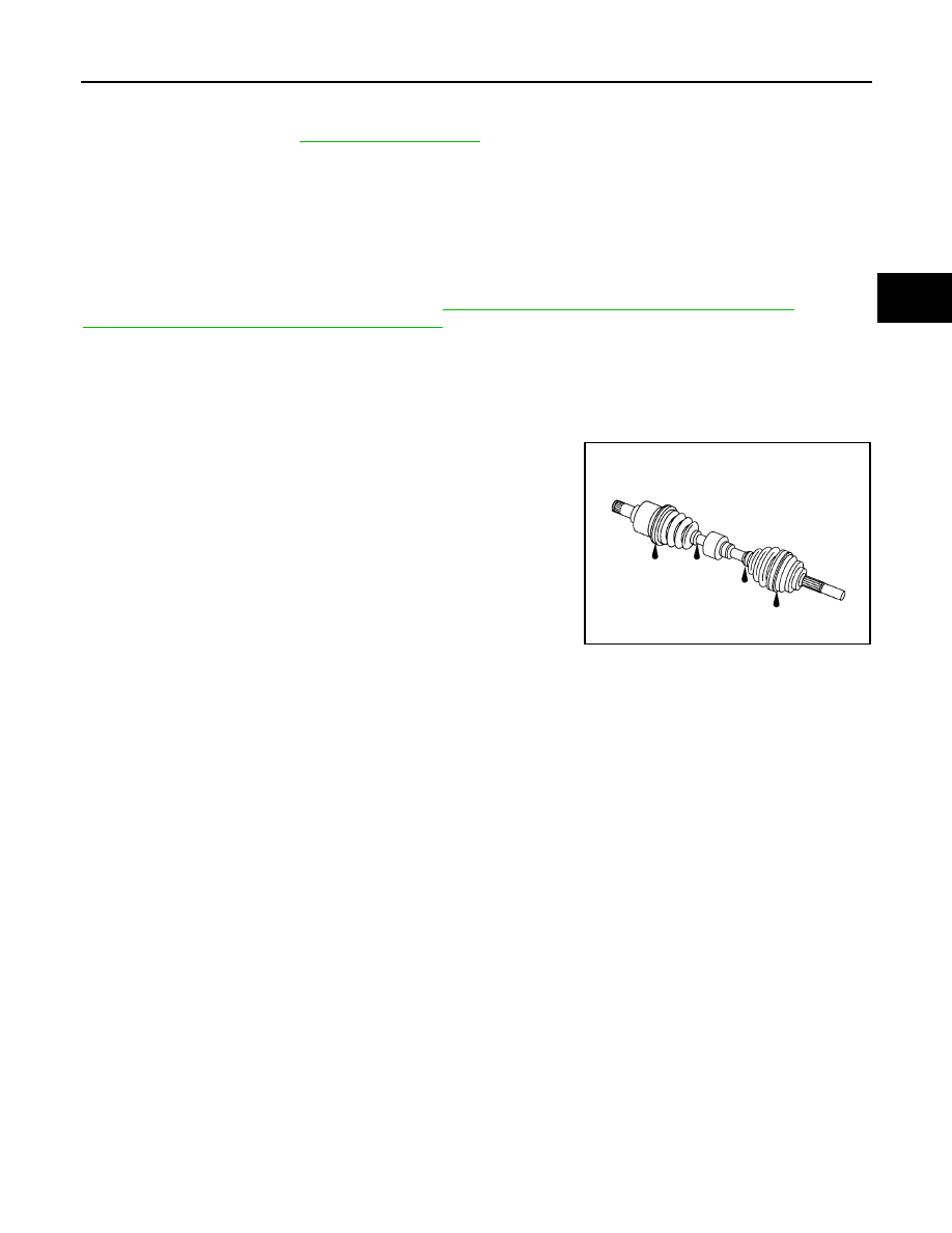
FRONT DRIVE SHAFT
Exploded View
INFOID:0000000009717901
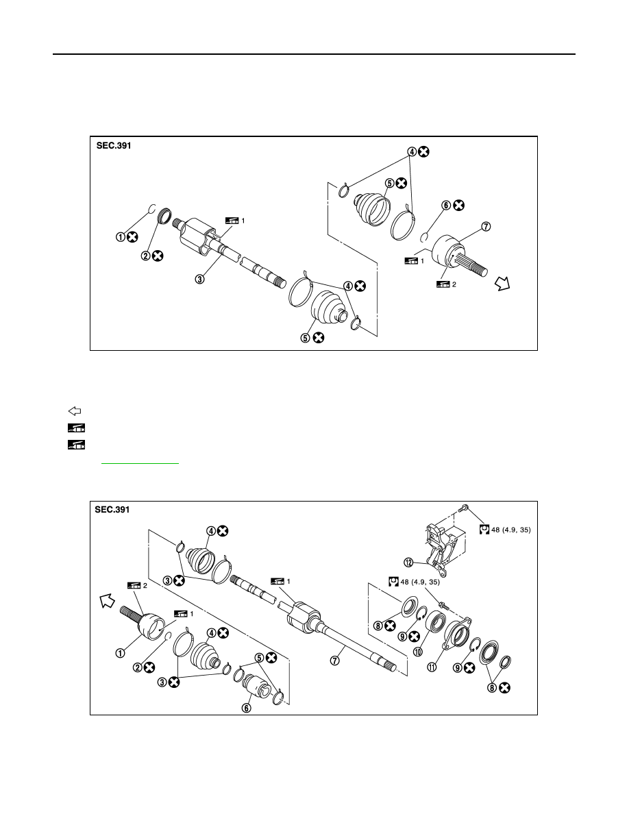
LEFT SIDE
RIGHT SIDE
1.
Circular clip
2.
Dust shield
3.
Housing assembly
4.
Boot band
5.
Boot
6.
Circular clip
7.
Joint sub-assembly
: Wheel side
1: Fill NISSAN Genuine grease or equivalent.
2: Apply paste [service parts (440037S000)].
Refer to
for symbols not described on the above.
JPDIF0243ZZ
1.
Joint sub-assembly
2.
Circular clip
3.
Boot band
4.
Boot
5.
Damper band
6.
Dynamic damper
7.
Housing assembly
8.
Dust shield
9.
Snap ring
10. Support bearing
11.
Baring housing
12. Support bearing bracket
JPDIF0254GB
Нет комментариевНе стесняйтесь поделиться с нами вашим ценным мнением.
Текст