Nissan Murano. Manual — part 754
FRONT WHEEL HUB AND KNUCKLE
FAX-11
< REMOVAL AND INSTALLATION >
[2WD]
C
E
F
G
H
I
J
K
L
M
A
B
FAX
N
O
P
REMOVAL AND INSTALLATION
FRONT WHEEL HUB AND KNUCKLE
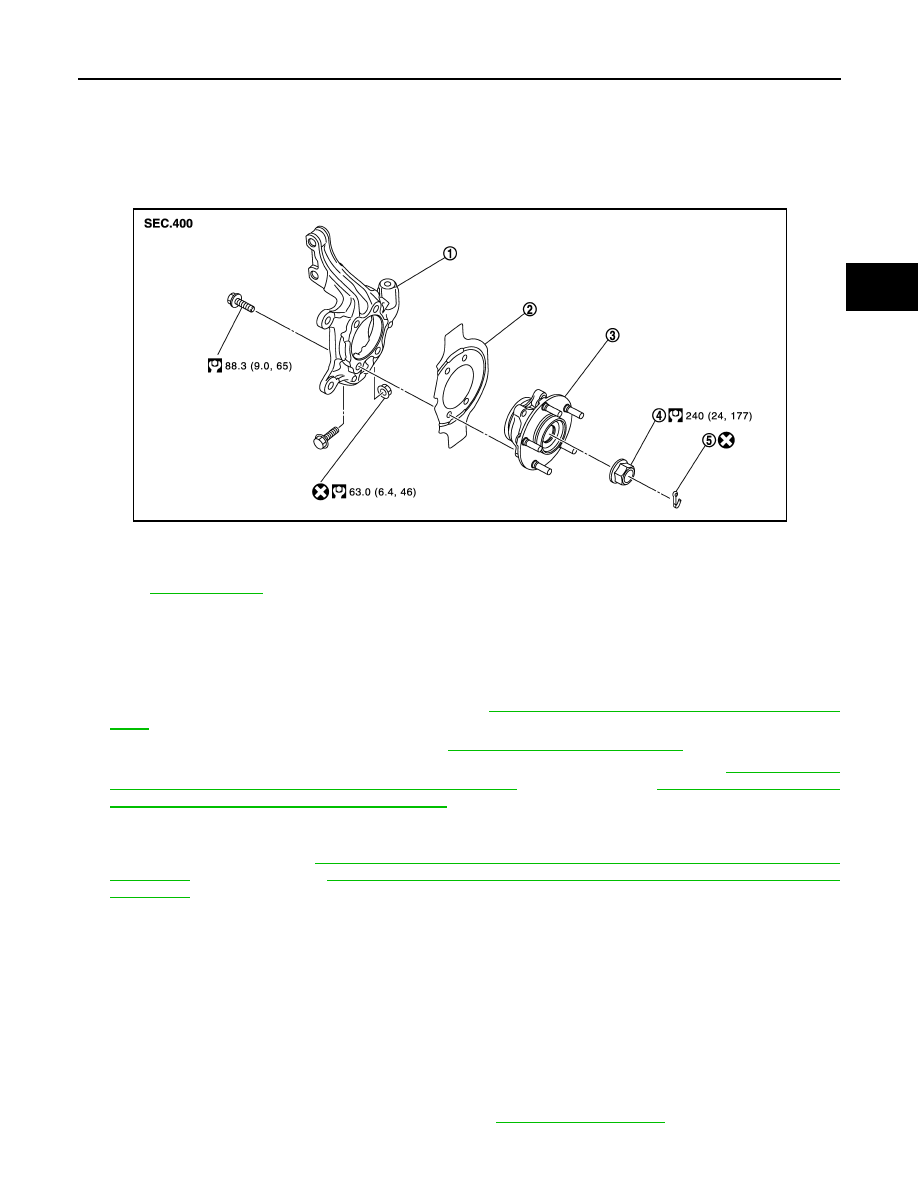
Exploded View
INFOID:0000000009717894
Removal and Installation
INFOID:0000000009717895
REMOVAL
1.
Remove tires with power tool.
2.
Remove wheel sensor and sensor harness. Refer to
BRC-123, "FRONT WHEEL SENSOR : Exploded
.
3.
Remove lock plate from strut assembly. Refer to
BR-22, "FRONT : Exploded View"
.
4.
Remove caliper assembly. Hang caliper assembly not to interfere with work. Refer to
CALIPER ASSEMBLY (1 PISTON TYPE) : Exploded View"
(1 PISTON TYPE),
ASSEMBLY (2 PISTON TYPE) : Exploded View"
(2 PISTON TYPE).
CAUTION:
Never depress brake pedal while brake caliper is removed.
5.
Remove disc rotor. Refer to
BR-39, "BRAKE CALIPER ASSEMBLY (1 PISTON TYPE) : Removal and
(1 PISTON TYPE),
BR-43, "BRAKE CALIPER ASSEMBLY (2 PISTON TYPE) : Removal and
(2 PISTON TYPE).
6.
Remove cotter pin, and then loosen wheel hub lock nut with power tool.
7.
Patch wheel hub lock nut with a piece of wood. Hammer the wood to disengage wheel hub and bearing
assembly from drive shaft.
CAUTION:
• Never place drive shaft joint at an extreme angle. Also be careful not to overextend slide joint.
• Never allow drive shaft to hang down without support for joint sub-assembly, shaft and the other
parts.
NOTE:
Use suitable puller, if wheel hub and bearing assembly and drive shaft cannot be separated even after
performing the above procedure.
8.
Remove wheel hub lock nut.
9.
Remove strut assembly from steering knuckle. Refer to
.
1.
Steering knuckle
2.
Splash guard
3.
Wheel hub and bearing assembly
4.
Wheel hub lock nut
5.
Cotter pin
Refer to
JPDIF0274GB
FAX-12
< REMOVAL AND INSTALLATION >
[2WD]
FRONT WHEEL HUB AND KNUCKLE
10. Remove drive shaft from wheel hub and bearing assembly, suspend the drive shaft with suitable wire.
11. Temporarily tighten strut assembly and steering knuckle.
12. Remove wheel hub and bearing assembly, and then remove splash guard.
13. Remove steering outer socket from steering knuckle. Refer to
.
14. Remove steering knuckle from transverse link.
15. Remove steering knuckle from strut assembly.
INSTALLATION
Note the following, and install in the reverse order of the removal.
• Clean the matching surface of wheel hub lock nut and wheel hub and bearing assembly.
CAUTION:
Never apply lubricating oil to these matching surface.
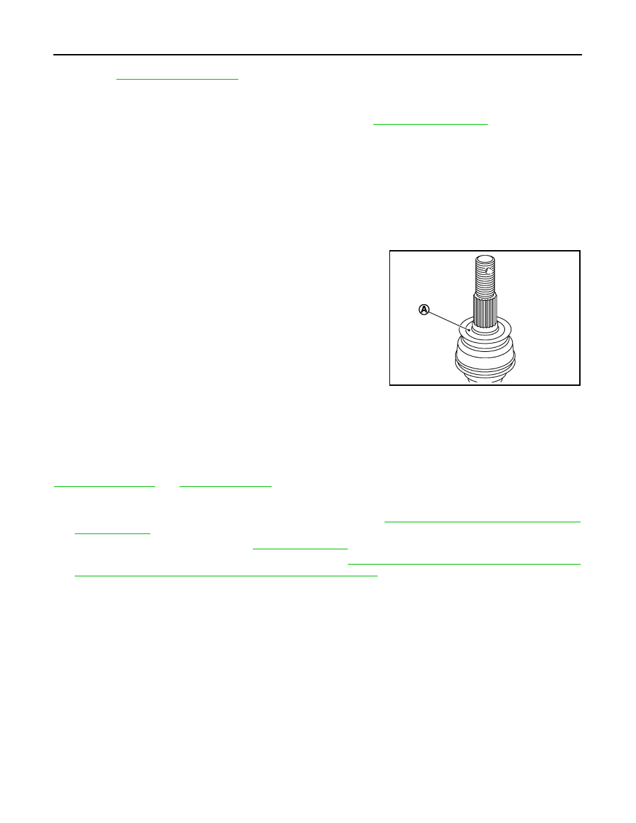
• Clean the matching surface of drive shaft and wheel hub and bearing assembly.
CAUTION:
Apply paste [service parts (440037S000)] to cover entire flat
surface (A) of joint sub-assembly of drive shaft.
• Never use a power tool to tighten the wheel hub lock nut.
• Perform the final tightening of each of parts under unladen condi-
tions, which were removed when removing wheel hub and bearing
assembly and axle housing.
• Never reuse cotter pin.
Inspection
INFOID:0000000009717896
INSPECTION AFTER REMOVAL
Check components for deformation, cracks, and other damage. Replace if necessary.
Ball Joint Inspection
Check boots of transverse link and steering outer socket ball joint for breakage, axial play, and torque. Refer to
.
INSPECTION AFTER INSTALLATION
1.
Check wheel sensor harness for proper connection. Refer to
BRC-123, "FRONT WHEEL SENSOR :
.
2.
Check the wheel alignment. Refer to
.
3.
Adjust neutral position of steering angle sensor. Refer to
BRC-9, "ADJUSTMENT OF STEERING ANGLE
SENSOR NEUTRAL POSITION : Special Repair Requirement"
.
Amount paste
: 1.0 – 3.0 g (0.04 – 0.10 oz)
JPDIG0122ZZ
FRONT DRIVE SHAFT BOOT
FAX-13
< REMOVAL AND INSTALLATION >
[2WD]
C
E
F
G
H
I
J
K
L
M
A
B
FAX
N
O
P
FRONT DRIVE SHAFT BOOT
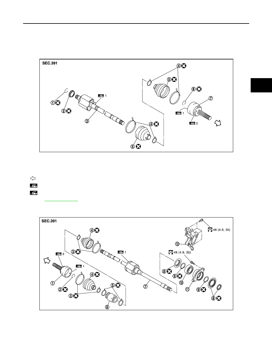
Exploded View
INFOID:0000000009717897
LEFT SIDE
RIGHT SIDE
1.
Circular clip
2.
Dust shield
3.
Housing assembly
4.
Boot band
5.
Boot
6.
Circular clip
7.
Joint sub-assembly
: Wheel side
1: Fill NISSAN Genuine grease or equivalent.
2: Apply paste [service parts (440037S000)].
Refer to
for symbols not described on the above.
JPDIF0243ZZ
1.
Joint sub-assembly
2.
Circular clip
3.
Boot band
4.
Boot
5.
Damper band
6.
Dynamic damper
7.
Housing assembly
8.
Dust shield
9.
Snap ring
10. Support bearing
11.
Baring housing
12. Support bearing bracket
JPDIF0254GB
FAX-14
< REMOVAL AND INSTALLATION >
[2WD]
FRONT DRIVE SHAFT BOOT
WHEEL SIDE
WHEEL SIDE : Removal and Installation
INFOID:0000000009717898
REMOVAL
1.
Remove tires with power tool.
2.
Remove wheel sensor and sensor harness. Refer to
BRC-123, "FRONT WHEEL SENSOR : Exploded
.
3.
Remove lock plate from strut assembly. Refer to
BR-22, "FRONT : Exploded View"
.
4.
Remove caliper assembly. Hang caliper assembly not to interfere with work. Refer to
CALIPER ASSEMBLY (1 PISTON TYPE) : Exploded View"
(1 PISTON TYPE),
ASSEMBLY (2 PISTON TYPE) : Exploded View"
(2 PISTON TYPE).
CAUTION:
Never depress brake pedal while brake caliper is removed.
5.
Remove disc rotor. Refer to
BR-35, "BRAKE PAD (1 PISTON TYPE) : Removal and Installation"
BR-37, "BRAKE PAD (2 PISTON TYPE) : Removal and Installation"
(2 PISTON TYPE).
6.
Remove cotter pin, and then loosen wheel hub lock nut with power tool.
7.
Patch wheel hub lock nut with a piece of wood. Hammer the wood to disengage wheel hub and bearing
assembly from drive shaft.
CAUTION:
• Never place drive shaft joint at an extreme angle. Also be careful not to overextend slide joint.
• Never allow drive shaft to hang down without support for joint sub-assembly, housing assembly
and the other parts.
NOTE:
Use suitable puller, if wheel hub and bearing assembly and drive shaft cannot be separated even after
performing the above procedure.
8.
Remove wheel hub lock nut.
9.
Remove strut assembly from steering knuckle. Refer to
.
10. Remove drive shaft from wheel hub and bearing assembly.
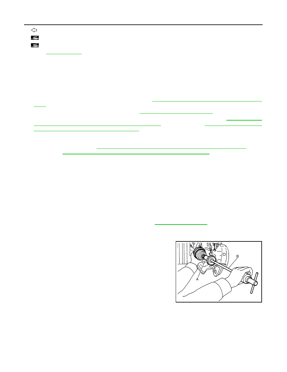
11. Remove boot bands, and then remove boot from joint sub-assembly.
12. Screw drive shaft puller (A) into joint sub-assembly screw part to
a length of 30 mm (1.18 in) or more. Support drive shaft with one
hand and pull out joint sub-assembly with a sliding hammer (B)
from housing assembly.
CAUTION:
• Align a sliding hammer and drive shaft and remove them
by pulling firmly and uniformly.
• If joint sub-assembly cannot be pulled out, try after
removing drive shaft from vehicle.
: Wheel side
1: Fill NISSAN Genuine grease or equivalent.
2: Apply paste [service parts (440037S000)].
Refer to
for symbols not described on the above.
JPDIF0022ZZ
Нет комментариевНе стесняйтесь поделиться с нами вашим ценным мнением.
Текст