Nissan Murano. Manual — part 641
EM-138
< UNIT DISASSEMBLY AND ASSEMBLY >
CYLINDER BLOCK
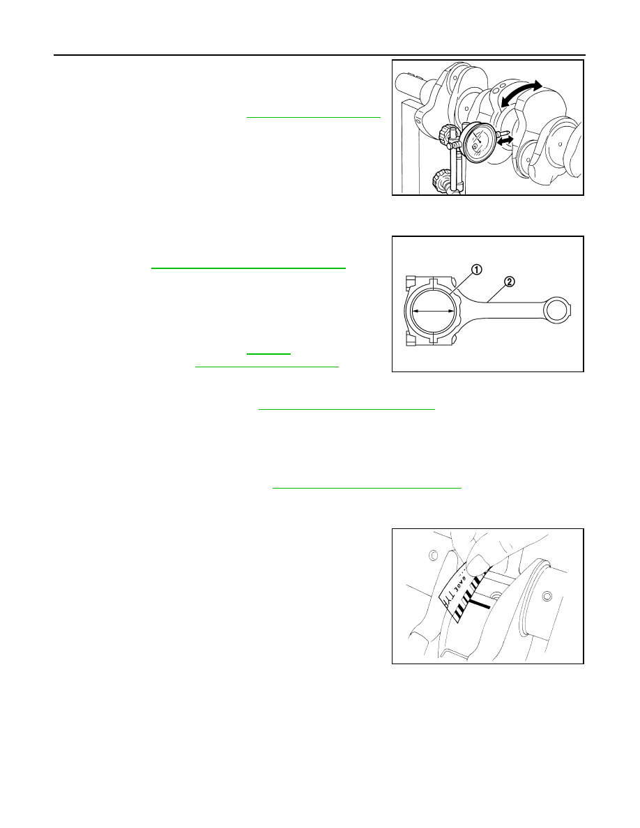
• Place a dial indicator straight up on the No. 3 journal.
• While rotating crankshaft, read the movement of the pointer on a
dial indicator. (Total indicator reading)
• If it exceeds the limit, replace crankshaft.
CONNECTING ROD BEARING OIL CLEARANCE
Method by Calculation
• Install connecting rod bearings (1) to connecting rod (2) and con-
necting rod cap, and tighten connecting rod bolts to the specified
torque. Refer to
EM-123, "Disassembly and Assembly"
for the
tightening procedure.
• Measure the inner diameter of connecting rod bearing with an
inside micrometer.
(Oil clearance) = (Connecting rod bearing inner diameter) – (Crank-
shaft pin journal diameter)
• If the calculated value exceeds the limit, select proper connecting
rod bearing according to connecting rod big end diameter and crankshaft pin journal diameter to obtain the
specified bearing oil clearance. Refer to
EM-142, "Connecting Rod Bearing"
Method of Using Plastigage
• Remove oil and dust on crankshaft pin journal and the surfaces of each bearing completely.
• Cut a plastigage slightly shorter than the bearing width, and place it in crankshaft axial direction, avoiding oil
holes.
• Install connecting rod bearings to connecting rod and connecting rod bearing cap, and tighten connecting
rod bolts to the specified torque. Refer to
EM-123, "Disassembly and Assembly"
dure.
CAUTION:
Never rotate crankshaft.
• Remove connecting rod bearing cap and bearings, and using the
scale on the plastigage bag, measure the plastigage width.
NOTE:
The procedure when the measured value exceeds the limit is
same as that described in the “Method by Calculation”.
MAIN BEARING OIL CLEARANCE
Method by Calculation
Standard and limit
: Refer to
.
SEM346D
Standard and limit
: Refer to
.
JPBIA0230ZZ
JPBIA0231ZZ
CYLINDER BLOCK
EM-139
< UNIT DISASSEMBLY AND ASSEMBLY >
C
D
E
F
G
H
I
J
K
L
M
A
EM
N
P
O
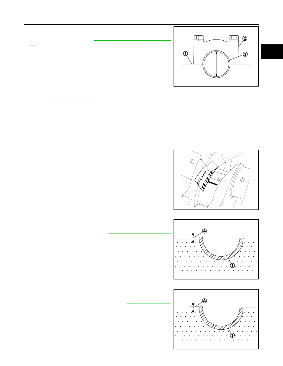
• Install main bearings (3) to cylinder block (1) and main bearing
caps (2), and main bearing cap bolts with main bearing beam to
the specified torque. Refer to
EM-123, "Disassembly and Assem-
• Measure the inner diameter of main bearing with a bore gauge.
(Oil clearance) = (Main bearing inner diameter) – (Crankshaft main
journal diameter)
• If the calculated value exceeds the limit, select proper main bear-
ing according to main bearing inner diameter and crankshaft main
journal diameter to obtain the specified bearing oil clearance.
Refer to
.
Method of Using Plastigage
• Remove engine oil and dust on crankshaft journal and the surfaces of each bearing completely.
• Cut a plastigage slightly shorter than the bearing width, and place it in crankshaft axial direction, avoiding oil
holes.
• Install main bearing to cylinder block and main bearing caps, and tighten main bearing cap bolts with main
bearing beam to the specified torque. Refer to
EM-123, "Disassembly and Assembly"
for the tightening pro-
cedure.
CAUTION:
Never rotate crankshaft.
• Remove main bearing caps and bearings, and using the scale on
the plastigage bag, measure the plastigage width.
NOTE:
The procedure when the measured value exceeds the limit is
same as that described in the “Method by Calculation”.
MAIN BEARING CRUSH HEIGHT
• When main bearing cap is removed after being tightened to the
specified torque with main bearings (1) installed, the tip end of
bearing must protrude. Refer to
for the tightening procedure.
• If the standard is not met, replace main bearings.
CONNECTING ROD BEARING CRUSH HEIGHT
• When connecting rod bearing cap is removed after being tightened
to the specified torque with connecting rod bearings (1) installed,
the tip end of bearing must protrude. Refer to
for the tightening procedure.
• If the standard is not met, replace connecting rod bearings.
Standard and limit
: Refer to
.
JPBIA0232ZZ
JPBIA0231ZZ
A
: Crush height
Standard
: There must be crush height.
JPBIA0233ZZ
A
: Crush height
Standard
: There must be crush height.
JPBIA0233ZZ
EM-140
< UNIT DISASSEMBLY AND ASSEMBLY >
CYLINDER BLOCK
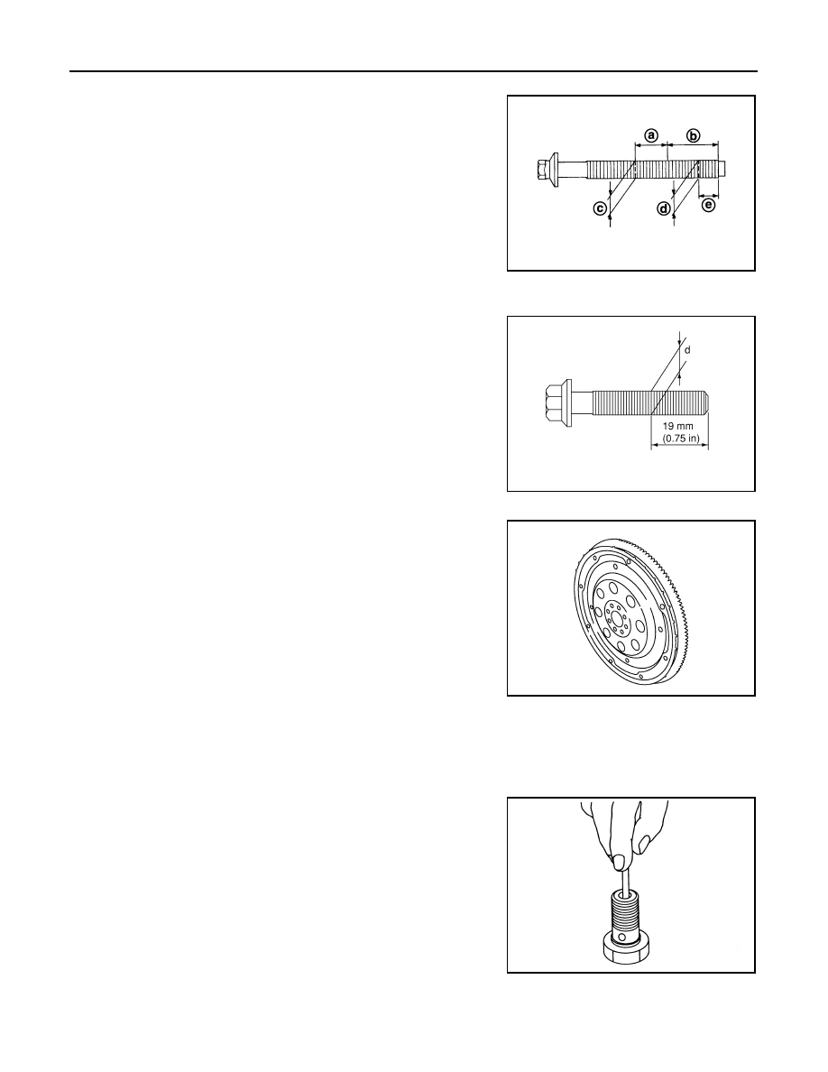
MAIN BEARING CAP BOLT OUTER DIAMETER
• Measure the outer diameters (c), (d) at two positions as shown in
the figure.
• If reduction appears in (a) range, regard it (c).
• If it exceeds the limit (large difference in dimensions), replace main
bearing cap bolt with new one.
CONNECTING ROD BOLT OUTER DIAMETER
• Measure the outer diameter (d) at position shown in the figure.
• If the reduction appears in a position other than (d), regard it as (d).
• When (d) exceeds the limit (when it becomes thinner), replace
connecting rod bolt with new one.
DRIVE PLATE
• Check drive plate and signal plate for deformation or damage.
CAUTION:
• Never disassemble drive plate.
• Never place drive plate with signal plate facing down.
• When handling signal plate, take care not to damage or
scratch it.
• Handle signal plate in a manner that prevents it from becom-
ing magnetized.
• If anything is found, replace drive plate.
OIL JET
• Check nozzle for deformation and damage.
• Blow compressed air from nozzle, and check for clogs.
• If it is not satisfied, clean or replace oil jet.
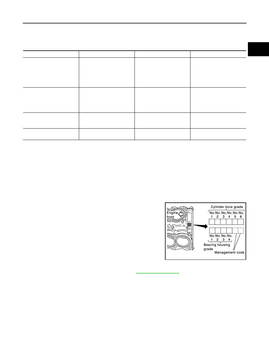
OIL JET RELIEF VALVE
• Using a clean plastic stick, press check valve in oil jet relief valve.
Check that valve moves smoothly with proper reaction force.
• If it is not satisfied, replace oil jet relief valve.
a
: 20 mm (0.79 in)
b
: 30 mm (1.18 in)
e
: 10 mm (0.39 in)
Limit [(d) – (c)]
: 0.11 mm (0.0043 in)
JPBIA0234ZZ
Standard
: 7.90 - 8.00 mm (0.3110 - 0.3150 in)
Limit
: 7.75 mm (0.3051 in)
PBIC0912E
JPBIA0192ZZ
EMU0468D
HOW TO SELECT PISTON AND BEARING
EM-141
< UNIT DISASSEMBLY AND ASSEMBLY >
C
D
E
F
G
H
I
J
K
L
M
A
EM
N
P
O
HOW TO SELECT PISTON AND BEARING
Description
INFOID:0000000009718009
*: For the service parts, the grade for fitting cannot be selected between piston pin and connecting rod. (Only “0” grade is available.) The
information at the shipment from the plant is described as a reference.
• The identification grade stamped on each part is the grade for the dimension measured in new condition.
This grade cannot apply to reused parts.
• For reused or repaired parts, measure the dimension accurately. Determine the grade by comparing the
measurement with the values of each selection table.
• For details of the measurement method of each part, the reuse standards and the selection method of the
selective fitting parts, refer to the text.
Piston
INFOID:0000000009718010
WHEN NEW CYLINDER BLOCK IS USED
Check the cylinder bore grade (“1”, “2” or “3”) on rear side of cylinder
block, and select piston of the same grade.
NOTE:
Piston is available with piston pin as a set for the service part. (Only
“0” grade piston pin is available.)
WHEN CYLINDER BLOCK IS REUSED
1.
Measure the cylinder bore inner diameter. Refer to
2.
Determine the bore grade by comparing the measurement with the values under the cylinder bore inner
diameter of the “PISTON SELECTION TABLE”.
Selection points
Selection parts
Selection items
Selection methods
Between cylinder block and
crankshaft
Main bearing
Main bearing grade
(bearing thickness)
Determined by match of cylin-
der block bearing housing
grade (inner diameter of hous-
ing) and crankshaft journal
grade (outer diameter of jour-
nal)
Between crankshaft and con-
necting rod
Connecting rod bearing
Connecting rod bearing grade
(bearing thickness)
Combining service grades for
connecting rod big end diame-
ter and crankshaft pin outer di-
ameter determine connecting
rod bearing selection.
Between cylinder block and pis-
ton
Piston and piston pin assembly
(Piston is available together
with piston pin as assembly.)
Piston grade
(piston skirt diameter)
Piston grade = cylinder bore
grade (inner diameter of bore)
Between piston and connecting
rod*
—
—
—
SEM756G
Нет комментариевНе стесняйтесь поделиться с нами вашим ценным мнением.
Текст