Nissan Murano. Manual — part 639
EM-130
< UNIT DISASSEMBLY AND ASSEMBLY >
CYLINDER BLOCK
13. Install connecting rod bearing cap.
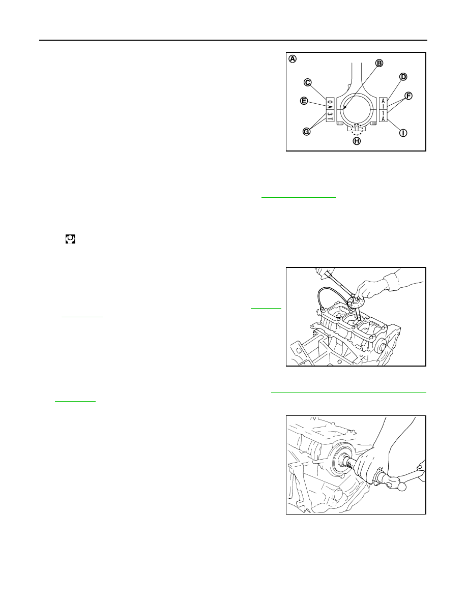
• Match the stamped cylinder number marks on connecting rod
with those on connecting rod bearing cap to install.
• Be sure that front mark (H) on connecting rod bearing cap is facing front of the engine.
14. Tighten connecting rod bolt as follows:
a.
Inspect the outer diameter of connecting rod bolt. Refer to
.
b.
Apply engine oil to the threads and seats of connecting rod bolts.
c.
Tighten connecting rod bolts.
d.
Then tighten all connecting rod bolts 90 degrees clockwise (angle tightening).
CAUTION:
Always use the angle wrench [SST: KV10112100 (BT8653-
A)]. Avoid tightening based on visual check alone.
• After tightening connecting rod bolts, check that crankshaft
rotates smoothly.
• Check the connecting rod side clearance. Refer to
.
15. Install baffle plate to main bearing beam.
16. Install new rear oil seal retainer to cylinder block. Refer to
EM-109, "REAR OIL SEAL : Removal and
.
17. Install pilot converter.
• With drift [outer diameter: approximately 33 mm (1.30 in)],
press-fit as far as it will go.
A
: Sample codes
B
: Bearing stopper groove
C
: Small-end diameter grade
D
: Standard stamp
E
: Weight grade
F
: Cylinder No.
G
: Management code
I
: Management code
JPBIA0208ZZ
: 19.6 N·m (2.0 kg-m, 14 ft-lb)
SEM953E
PBIC0899E
CYLINDER BLOCK
EM-131
< UNIT DISASSEMBLY AND ASSEMBLY >
C
D
E
F
G
H
I
J
K
L
M
A
EM
N
P
O
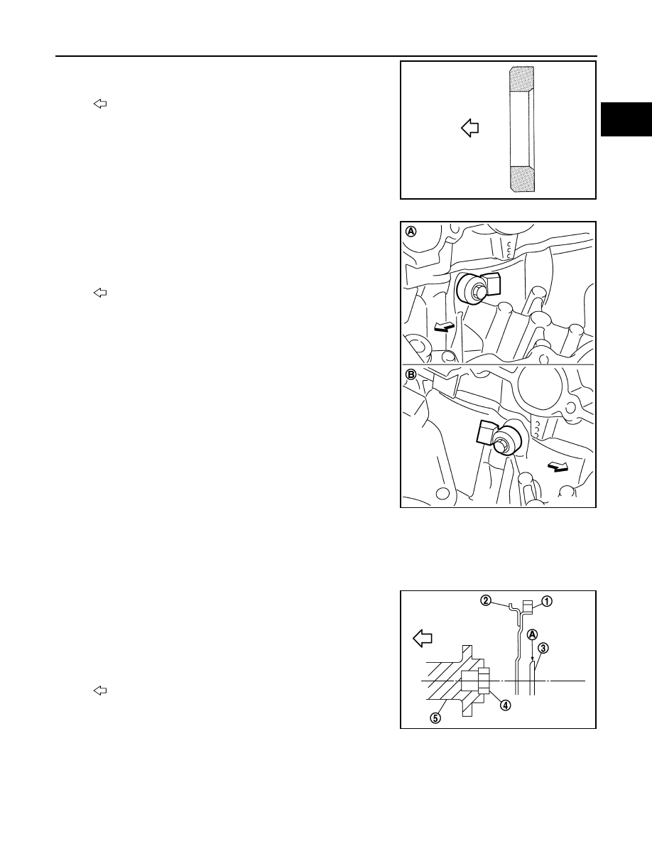
• Press-fit pilot converter with its chamfer facing crankshaft as
shown in the figure.
18. Install knock sensors.
• Install knock sensor so that connector faces the rear of the
engine.
• After installing knock sensor, connect harness connector, and
lay it out to rear of engine.
CAUTION:
• Never tighten mounting bolts while holding connector.
• If any impact by dropping is applied to knock sensor,
replace it with new one.
NOTE:
• Check that there is no foreign material on the cylinder block
mating surface and the back surface of knock sensor.
• Check that knock sensor does not interfere with other parts.
19. Note the following, assemble in the reverse order of disassembly after this step.
Drive plate
• When installing drive plate to crankshaft, be sure to correctly align crankshaft side dowel pin and drive
plate side dowel pin hole.
- If these are not aligned correctly, engine runs roughly and “MIL” turns on.
• Install drive plate (2) and reinforcement plate (3) as shown in
the figure.
• Holding ring gear with the pulley holder (commercial service
tool).
• Tighten mounting bolts crosswise over several times.
Inspection
INFOID:0000000009718008
CRANKSHAFT END PLAY
: Crankshaft side
JPBIA0210ZZ
A
: Bank 1
B
: Bank 2
: Engine front
JPBIA0211ZZ
1
: Ring gear
4
: Pilot converter
5
: Crankshaft
A
: Rounded
: Engine front
JPBIA0212ZZ
EM-132
< UNIT DISASSEMBLY AND ASSEMBLY >
CYLINDER BLOCK
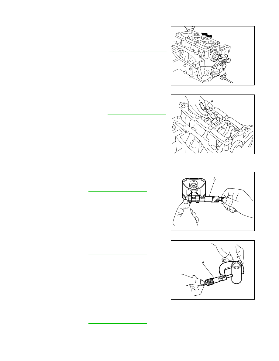
• Measure the clearance between thrust bearings and crankshaft
arm when crankshaft is moved fully forward or backward with a dial
indicator.
• If the measured value exceeds the limit, replace thrust bearings,
and measure again. If it still exceeds the limit, replace crankshaft
also.
CONNECTING ROD SIDE CLEARANCE
• Measure the side clearance between connecting rod and crank-
shaft arm with a feeler gauge (A).
• If the measured value exceeds the limit, replace connecting rod,
and measure again. If it still exceeds the limit, replace crankshaft
also.
PISTON TO PISTON PIN OIL CLEARANCE
Piston Pin Hole Diameter
Measure the inner diameter of piston pin hole with an inside
micrometer (A).
Piston Pin Outer Diameter
Measure the outer diameter of piston pin with a micrometer (A).
Piston to Piston Pin Oil Clearance
(Piston to piston pin oil clearance) = (Piston pin hole diameter) – (Piston pin outer diameter)
• If the calculated value is out of the standard, replace piston and piston pin assembly.
• When replacing piston and piston pin assembly, refer to
.
NOTE:
• Piston is available together with piston pin as assembly.
Standard and limit
: Refer to
.
EMQ0196D
Standard and limit
: Refer to
JPBIA0536ZZ
Standard
: Refer to
JPBIA0217ZZ
Standard
: Refer to
JPBIA0218ZZ
Standard
: Refer to
CYLINDER BLOCK
EM-133
< UNIT DISASSEMBLY AND ASSEMBLY >
C
D
E
F
G
H
I
J
K
L
M
A
EM
N
P
O
• Piston pin (piston pin hole) grade is provided only for the parts installed at the plant. For service parts, no
piston pin grades can be selected. (Only “0” grade is available.)
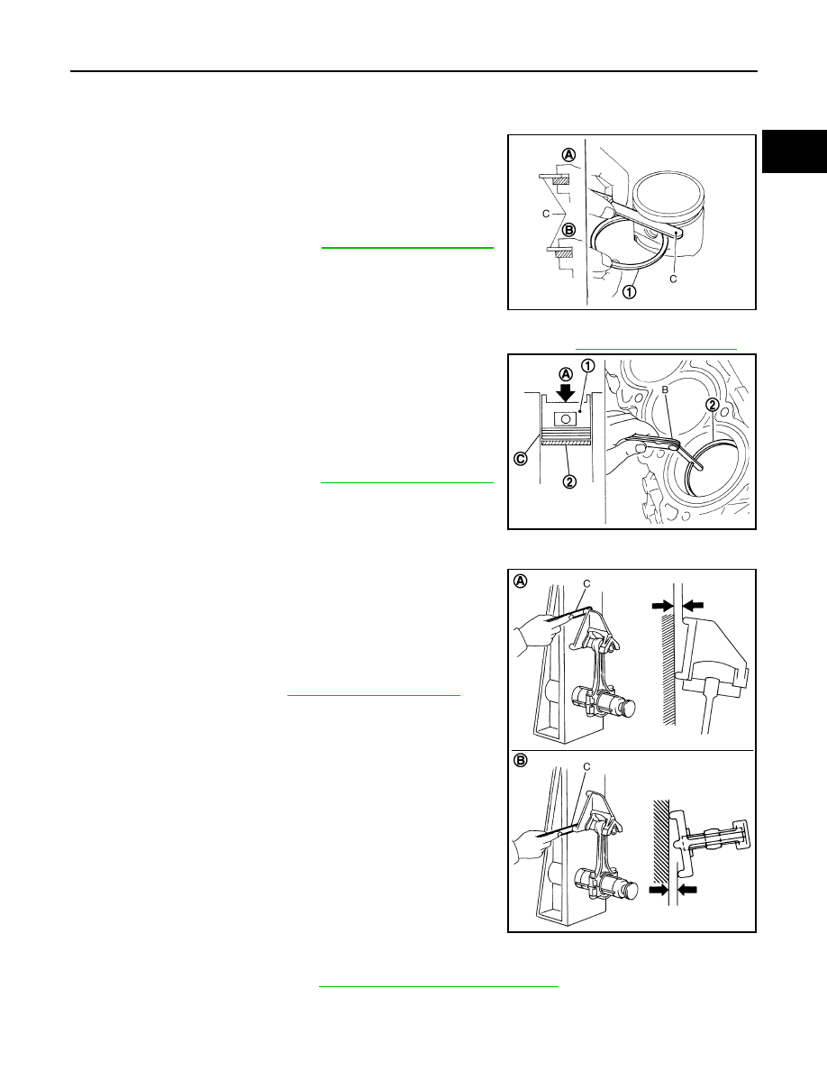
PISTON RING SIDE CLEARANCE
• Measure the side clearance of piston ring (1) and piston ring
groove with a feeler gauge (C).
• If the measured value exceeds the limit, replace piston ring, and
measure again. If it still exceeds the limit, replace piston also.
PISTON RING END GAP
• Check that the cylinder bore inner diameter is within the specification. Refer to
• Lubricate with new engine oil to piston (1) and piston ring (2), and
then insert piston ring until middle of cylinder with piston, and mea-
sure the piston ring end gap with a feeler gauge (B).
• If the measured value exceeds the limit, replace piston ring, and
measure again. If it still exceeds the limit, rebore cylinder and use
oversize piston and piston rings.
CONNECTING ROD BEND AND TORSION
• Check with a connecting rod aligner.
• If it exceeds the limit, replace connecting rod assembly.
CONNECTING ROD BIG END DIAMETER
• Install connecting rod bearing cap without installing connecting rod bearing, and tightening connecting rod
bolts to the specified torque. Refer to
EM-123, "Disassembly and Assembly"
for the tightening procedure.
A
: NG
B
: OK
Standard and limit
: Refer to
.
JPBIA0219ZZ
A
: Press-fit
C
: Measuring point
Standard and limit
: Refer to
JPBIA0220ZZ
A
: Bend
B
: Torsion
C
: Feeler gauge
Bend limit
: Refer to
Torsion limit
JPBIA0221ZZ
Нет комментариевНе стесняйтесь поделиться с нами вашим ценным мнением.
Текст