Nissan Murano. Manual — part 593

EC-482
< ECU DIAGNOSIS INFORMATION >
[VQ35DE]
ECM
47
(G)
36
(B)
Sensor power supply
(Throttle position sensor)
—
[Ignition switch: ON]
5 V
48
(B/P)
—
Sensor ground
(Power steering pressure
sensor)
—
—
—
49
(L)
112
(B)
A/F sensor 1 (bank 1)
Input
[Engine is running]
• Warm-up condition
• Engine speed: 2,000 rpm
1.8 V
Output voltage varies with air fuel
ratio.
50
(L/Y)
56
(G/B)
Intake air temperature sensor
Input
[Engine is running]
0 - 4.8 V
Output voltage varies with intake
air temperature.
51
(R/Y)
44
(G/B)
Sensor power supply
(Battery current sensor)
—
[Ignition switch: ON]
5 V
52
(B/R)
—
Sensor ground
(Engine coolant temperature
sensor/Engine oil tempera-
ture sensor)
—
—
—
53
(V)
57
(LG)
A/F sensor 1 (bank 2)
Input
[Ignition switch: ON]
2.2 V
54
(G)
52
(B/R)
Engine oil temperature sensor
Input
[Engine is running]
0 - 4.8 V
Output voltage varies with engine
oil temperature.
55
(SB)
48
(Y)
Sensor power supply
(Power steering pressure
sensor)
—
[Ignition switch: ON]
5 V
56
(G/B)
—
Sensor ground
(Mass air flow sensor/Intake
air temperature sensor)
—
—
—
57
(LG)
112
(B)
A/F sensor 1 (bank 2)
Input
[Engine is running]
• Warm-up condition
• Engine speed: 2,000 rpm
1.8 V
Output voltage varies with air fuel
ratio.
58
(O)
56
(G/B)
Mass air flow sensor
Input
[Engine is running]
• Warm-up condition
• Idle speed
0.9 - 1.2 V
[Engine is running]
• Warm-up condition
• Engine speed: 2,500 rpm
1.6 - 1.9 V
59
(G/W)
64
(B/R)
Sensor power supply
[Camshaft position sensor
(PHASE) (bank 1)]
—
[Ignition switch: ON]
5 V
60
(Y/B)
—
Sensor ground
[Crankshaft position sensor
(POS)]
—
—
—
61
(B)
67
(—)
Knock sensor (bank 1)
Input
[Engine is running]
• Idle speed
2.5 V*
1
62
(W)
67
(—)
Knock sensor (bank 2)
Input
[Engine is running]
• Idle speed
2.5 V*
1
63
(R/W)
68
(Y/G)
Sensor power supply
[Camshaft position sensor
(PHASE) (bank 2)]
—
[Ignition switch: ON]
5 V
64
(B/R)
—
Sensor ground
[Camshaft position sensor
(PHASE) (bank 1)]
—
—
—
Terminal No.
Description
Condition
Value
(Approx.)
+
-–
Signal name
Input/
Output
ECM
EC-483
< ECU DIAGNOSIS INFORMATION >
[VQ35DE]
C
D
E
F
G
H
I
J
K
L
M
A
EC
N
P
O
65
(W/B)
60
(Y/B)
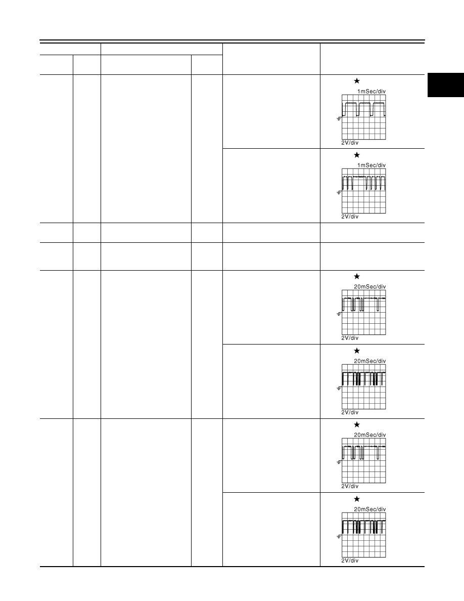
Crankshaft position sensor
(POS)
Input
[Engine is running]
• Warm-up condition
• Idle speed
NOTE:
The pulse cycle changes de-
pending on rpm at idle
4.0 - 5.0 V
[Engine is running]
• Engine speed: 2,000 rpm
4.0 - 5.0 V
67
(—)
—
Sensor ground
(Knock sensor)
—
—
—
68
(Y/G)
—
Sensor ground
[Camshaft position sensor
(PHASE) (bank 2)]
—
—
—
69
(BR/W)
68
(Y/G)
Camshaft position sensor
(PHASE) (bank 2)
Input
[Engine is running]
• Warm-up condition
• Idle speed
NOTE:
The pulse cycle changes de-
pending on rpm at idle
3.0 - 5.0 V
[Engine is running]
• Engine speed is 2,000 rpm
3.0 - 5.0 V
70
(W/R)
64
(B/R)
Camshaft position sensor
(PHASE) (bank 1)
Input
[Engine is running]
• Warm-up condition
• Idle speed
NOTE:
The pulse cycle changes de-
pending on rpm at idle
3.0 - 5.0 V
[Engine is running]
• Engine speed is 2,000 rpm
3.0 - 5.0 V
Terminal No.
Description
Condition
Value
(Approx.)
+
-–
Signal name
Input/
Output
JMBIA0041GB
JMBIA0042GB
JMBIA0045GB
JMBIA0046GB
JMBIA0045GB
JMBIA0046GB

EC-484
< ECU DIAGNOSIS INFORMATION >
[VQ35DE]
ECM
72
(BR/W)
40
(G)
Sensor power supply
(Refrigerant pressure sensor)
—
[Ignition switch: ON]
5 V
75
(Y)
112
(B)
Intake valve timing control so-
lenoid valve (bank 2)
Output
[Engine is running]
• Warm-up condition
• Idle speed
BATTERY VOLTAGE
(11 - 14 V)
[Engine is running]
• Warm-up condition
• Engine speed: 2,000 rpm
7 - 12 V
76
(R/G)
60
(Y/B)
Sensor power supply
[Crankshaft position sensor
(POS)]
—
[Ignition switch: ON]
5 V
77
(W/L)
112
(B)
Power supply for ECM (Back-
up)
Input
[Ignition switch: OFF]
BATTERY VOLTAGE
(11 - 14 V)
78
(R/L)
112
(B)
Intake valve timing control so-
lenoid valve (bank 1)
Output
[Engine is running]
• Warm-up condition
• Idle speed
BATTERY VOLTAGE
(11 - 14 V)
[Engine is running]
• Warm-up condition
• Engine speed: 2,000 rpm
7 - 12 V
81
(W)
84
(B)
Accelerator pedal position
sensor 1
Input
[Ignition switch: ON]
• Engine stopped
• Accelerator pedal: Fully re-
leased
0.5 - 1.0 V
[Ignition switch: ON]
• Engine stopped
• Accelerator pedal: Fully de-
pressed
4.2 - 4.8 V
82
(O)
100
(G)
Accelerator pedal position
sensor 2
Input
[Ignition switch: ON]
• Engine stopped
• Accelerator pedal: Fully re-
leased
0.25 - 0.50 V
[Ignition switch: ON]
• Engine stopped
• Accelerator pedal: Fully de-
pressed
2.0 - 2.5 V
83
(BR)
84
(B)
Sensor power supply
(Accelerator pedal position
sensor 1)
—
[Ignition switch: ON]
5 V
84
(B)
—
Sensor ground
(Accelerator pedal position
sensor 1)
—
—
—
Terminal No.
Description
Condition
Value
(Approx.)
+
-–
Signal name
Input/
Output
JMBIA0038GB
JMBIA0038GB
ECM
EC-485
< ECU DIAGNOSIS INFORMATION >
[VQ35DE]
C
D
E
F
G
H
I
J
K
L
M
A
EC
N
P
O
85
(Y)
92
(BR)
ASCD steering switch
Input
[Ignition switch: ON]
• ASCD steering switch: OFF
4 V
[Ignition switch: ON]
• MAIN switch: Pressed
0 V
[Ignition switch: ON]
• CANCEL switch: Pressed
1 V
[Ignition switch: ON]
• RESUME/ACCELERATE
switch: Pressed
3 V
[Ignition switch: ON]
• SET/COAST switch: Pressed
2 V
86
(SB)
96
(GR)
EVAP control system pres-
sure sensor
Input
[Ignition switch: ON]
1.8 - 4.8 V
87
(GR)
100
(G)
Sensor power supply
(Accelerator pedal position
sensor 2)
—
[Ignition switch: ON]
5 V
88
(O)
—
Data link connector
Input/
Output
—
—
91
(L)
96
(GR)
Sensor power supply
(EVAP control system pres-
sure sensor)
—
[Ignition switch: ON]
5 V
92
(BR)
—
Sensor ground
(ASCD steering switch)
—
—
—
93
(BR)
112
(B)
Ignition switch
Input
[Ignition switch: OFF]
0 V
[Ignition switch: ON]
BATTERY VOLTAGE
(11 - 14 V)
94
(GR)
112
(B)
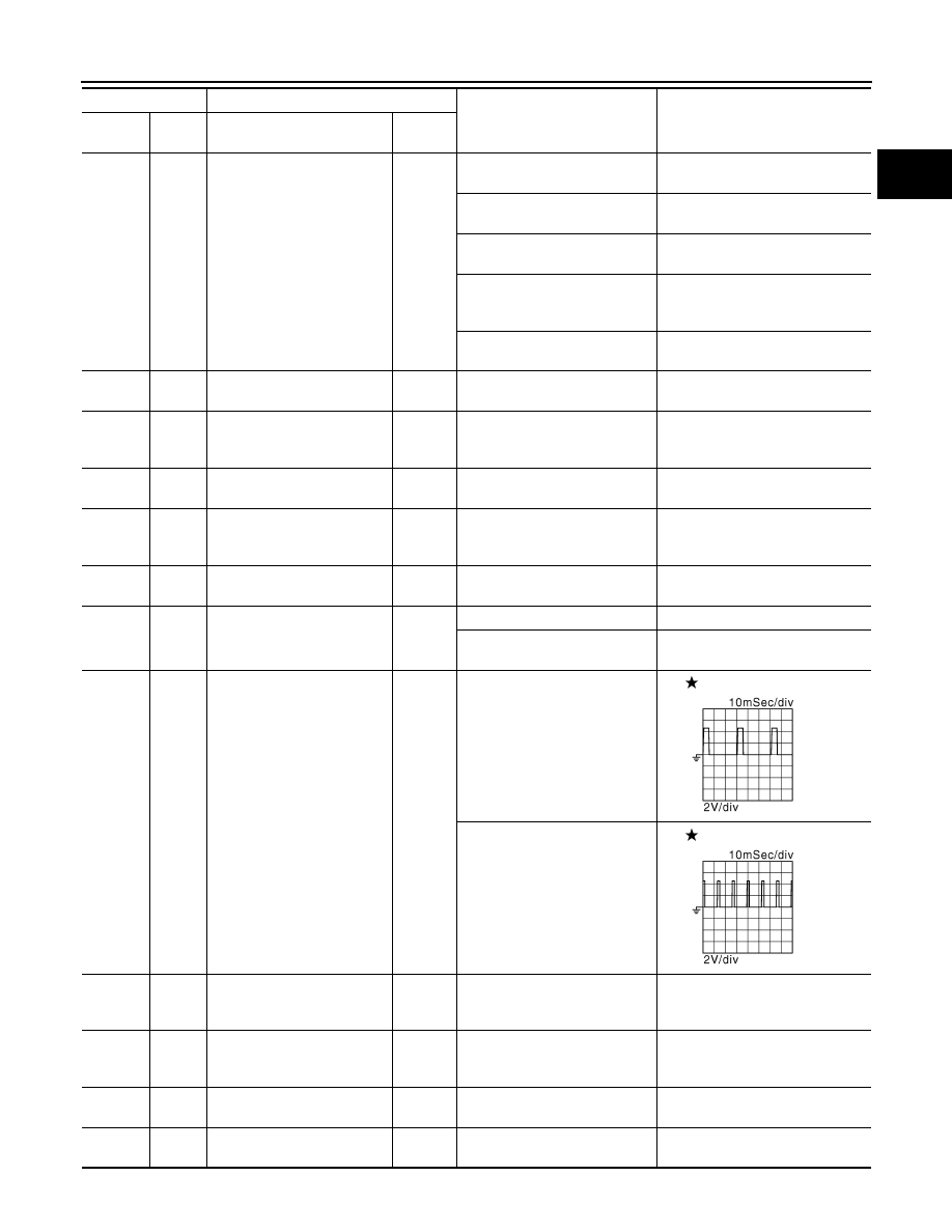
Engine speed output signal
Output
[Engine is running]
• Warm-up condition
• Idle speed
NOTE:
The pulse cycle changes de-
pending on rpm at idle
1 V
[Engine is running]
• Engine speed: 2,000 rpm
1 V
95
(Y)
104
(SB)
Fuel tank temperature sensor
Input
[Engine is running]
0 - 4.8 V
Output voltage varies with fuel tank
temperature.
96
(GR)
—
Sensor ground
(EVAP control system pres-
sure sensor)
—
—
—
97
(P)
—
CAN communication line
(CAN-L)
Input/
Output
—
—
98
(L)
—
CAN communication line
(CAN-H)
Input/
Output
—
—
Terminal No.
Description
Condition
Value
(Approx.)
+
-–
Signal name
Input/
Output
JMBIA0076GB
JMBIA0077GB
Нет комментариевНе стесняйтесь поделиться с нами вашим ценным мнением.
Текст