Nissan Murano. Manual — part 592
EC-478
< ECU DIAGNOSIS INFORMATION >
[VQ35DE]
ECM
5
(L)
112
(B)
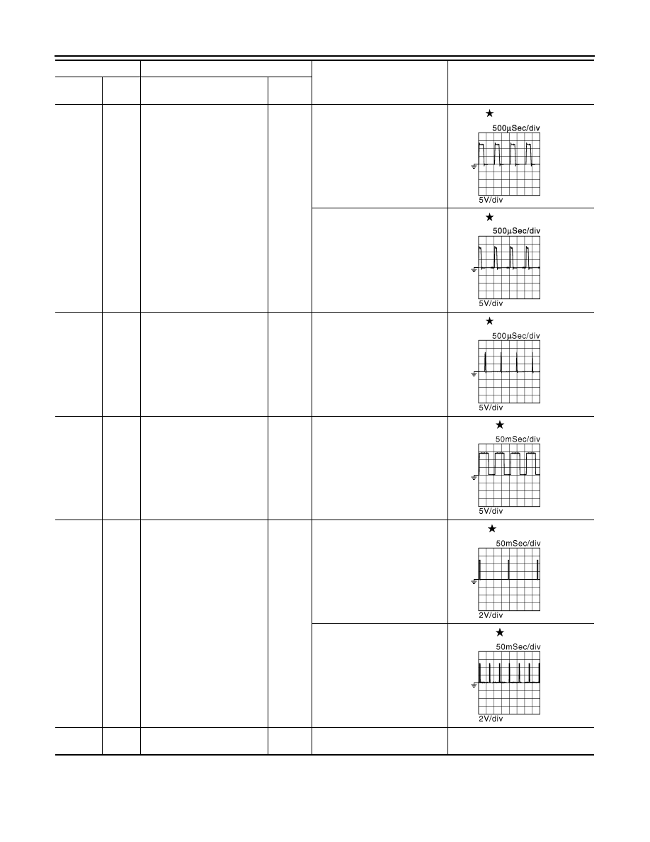
Throttle control motor (Open)
Output
[Ignition switch: ON]
• Engine stopped
• Selector lever: D position
• Accelerator pedal: Fully de-
pressed
0 - 14 V
[Ignition switch: ON]
• Engine stopped
• Selector lever: D position
• Accelerator pedal: Fully re-
leased
0 - 14 V
6
(P)
112
(B)
Throttle control motor (Close)
Output
[Ignition switch: ON]
• Engine stopped
• Selector lever: D position
• Accelerator pedal: Fully re-
leased
0 - 14 V
8
(SB)
112
(B)
A/F sensor 1 heater (bank 2)
Output
[Engine is running]
• Warm-up condition
• Idle speed
(More than 140 seconds after
starting engine)
2.9 - 8.8 V
9
(L/B)
112
(B)
Ignition signal No. 3
Output
[Engine is running]
• Warm-up condition
• Idle speed
NOTE:
The pulse cycle changes de-
pending on rpm at idle
0 - 0.2 V
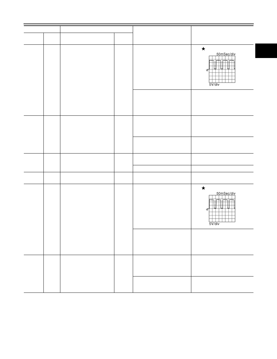
10
(G/R)
Ignition signal No. 2
11
(Y/R)
Ignition signal No. 1
18
(GR/R)
Ignition signal No. 6
[Engine is running]
• Warm-up condition
• Engine speed: 2,000 rpm
0.1 - 0.4 V
19
(P)
Ignition signal No. 5
21
(W)
Ignition signal No. 4
12
(B)
—
ECM ground
—
—
—
Terminal No.
Description
Condition
Value
(Approx.)
+
-–
Signal name
Input/
Output
JMBIA0031GB
JMBIA0032GB
JMBIA1125GB
JMBIA0030GB
JMBIA0035GB
JMBIA0036GB
ECM
EC-479
< ECU DIAGNOSIS INFORMATION >
[VQ35DE]
C
D
E
F
G
H
I
J
K
L
M
A
EC
N
P
O
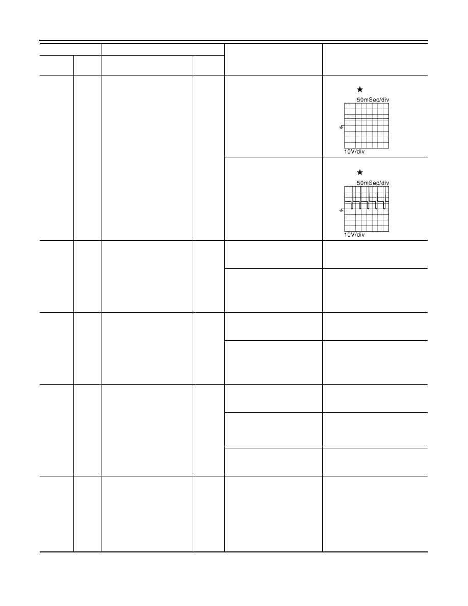
13
(P/B)
112
(B)
Heated oxygen sensor 2 heat-
er (bank 1)
Output
[Engine is running]
• Engine speed: Below 3,600
rpm after the following condi-
tions are met
- Engine: after warming up
- Keeping the engine speed be-
tween 3,500 and 4,000 rpm
for 1 minute and at idle for 1
minute under no load
10 V
[Ignition switch: ON]
• Engine stopped
[Engine is running]
• Engine speed: Above 3,600
rpm
BATTERY VOLTAGE
(11 - 14 V)
14
(GR)
112
(B)
Fuel pump relay
Output
[Ignition switch: ON]
• For 1 second after turning ig-
nition switch ON
[Engine is running]
0 - 1.5 V
[Ignition switch: ON]
• More than 1 second after turn-
ing ignition switch ON
BATTERY VOLTAGE
(11 - 14 V)
15
(O)
112
(B)
Throttle control motor relay
Output
[Ignition switch: ON
→
OFF]
0 - 1.0 V
→
BATTERY VOLTAGE
(11 - 14 V)
→
0 V
[Ignition switch: ON]
0 - 1.0 V
16
(B/Y)
—
ECM ground
—
—
—
17
(R)
112
(B)
Heated oxygen sensor 2 heat-
er (bank 2)
Output
[Engine is running]
• Engine speed: Below 3,600
rpm after the following condi-
tions are met
- Engine: after warming up
- Keeping the engine speed be-
tween 3,500 and 4,000 rpm
for 1 minute and at idle for 1
minute under no load
10 V
[Ignition switch: ON]
• Engine stopped
[Engine is running]
• Engine speed: Above 3,600
rpm
BATTERY VOLTAGE
(11 - 14 V)
24
(W/B)
112
(B)
ECM relay
(Self shut-off)
Output
[Engine is running]
[Ignition switch: OFF]
• A few seconds after turning
ignition switch OFF
0 - 1.5 V
[Ignition switch: OFF]
• More than a few seconds after
turning ignition switch OFF
BATTERY VOLTAGE
(11 - 14 V)
Terminal No.
Description
Condition
Value
(Approx.)
+
-–
Signal name
Input/
Output
JMBIA0902GB
JMBIA0902GB
EC-480
< ECU DIAGNOSIS INFORMATION >
[VQ35DE]
ECM
25
(P/L)
112
(B)
EVAP canister purge volume
control solenoid valve
Output
[Engine is running]
• Idle speed
• Accelerator pedal: Not de-
pressed even slightly, after
engine starting
BATTERY VOLTAGE
(11 - 14 V)
[Engine is running]
• Engine speed: approximately
2,000 rpm (More than 100
seconds after starting engine)
BATTERY VOLTAGE
(11 - 14 V)
26
(GR/B)
112
(B)
VIAS control solenoid valve 2
Output
[Engine is running]
• Warm-up condition
• Idle speed
BATTERY VOLTAGE
(11 - 14 V)
[Engine is running]
• Warm-up condition
• When revving engine up to
5,000 rpm quickly
BATTERY VOLTAGE (11 - 14 V)
↓
0 - 1.0 V
↓
BATTERY VOLTAGE (11 - 14 V)
27
(V)
112
(B)
VIAS control solenoid valve 1
Output
[Engine is running]
• Warm-up condition
• Idle speed
BATTERY VOLTAGE
(11 - 14 V)
[Engine is running]
• Warm-up condition
• When revving engine up to
5,000 rpm quickly
BATTERY VOLTAGE (11 - 14 V)
↓
0 - 1.0 V
↓
BATTERY VOLTAGE (11 - 14 V)
28
(BR/W)
112
(B)
Electronic controlled engine
mount control solenoid valve
Output
[Engine is running]
• Engine speed: For 2 seconds
after reaching 950 rpm or less
0 - 1.0 V
[Engine is running]
• Engine speed: After a lapse of
2 seconds after reaching 950
rpm or less
2.0 - 3.0 V
[Engine is running]
• Engine speed: 950 rpm or
more
BATTERY VOLTAGE
(11 - 14 V)
33
(W)
112
(B)
Heated oxygen sensor 2
(bank 1)
Input
[Engine is running]
• Revving engine from idle to
3,000 rpm quickly after the fol-
lowing conditions are met
- Engine: after warming up
- Keeping the engine speed be-
tween 3,500 and 4,000 rpm
for 1 minute and at idle for 1
minute under no load
0 - 1.0 V
Terminal No.
Description
Condition
Value
(Approx.)
+
-–
Signal name
Input/
Output
JMBIA0039GB
JMBIA0040GB

ECM
EC-481
< ECU DIAGNOSIS INFORMATION >
[VQ35DE]
C
D
E
F
G
H
I
J
K
L
M
A
EC
N
P
O
34
(W/L)
112
(B)
Heated oxygen sensor 2
(bank 2)
Input
[Engine is running]
• Revving engine from idle to
3,000 rpm quickly after the fol-
lowing conditions are met
- Engine: after warming up
- Keeping the engine speed be-
tween 3,500 and 4,000 rpm
for 1 minute and at idle for 1
minute under no load
0 - 1.0 V
35
(B)
—
Sensor ground
(Heated oxygen sensor 2)
—
—
—
36
(B)
—
Sensor ground
(Throttle position sensor)
—
—
—
37
(W)
112
(B)
Throttle position sensor 1
Input
[Ignition switch: ON]
• Engine stopped
• Selector lever: D position
• Accelerator pedal: Fully re-
leased
More than 0.36 V
[Ignition switch: ON]
• Engine stopped
• Selector lever: D position
• Accelerator pedal: Fully de-
pressed
Less than 4.75 V
38
(R)
112
(B)
Throttle position sensor 2
Input
[Ignition switch: ON]
• Engine stopped
• Selector lever: D position
• Accelerator pedal: Fully re-
leased
Less than 4.75 V
[Ignition switch: ON]
• Engine stopped
• Selector lever: D position
• Accelerator pedal: Fully de-
pressed
More than 0.36 V
39
(R)
40
(G)
Refrigerant pressure sensor
Input
[Engine is running]
• Warm-up condition
• Both A/C switch and blower
fan motor switch: ON (Com-
pressor operates)
1.0 - 4.0 V
40
(G)
—
Sensor ground
(Refrigerant pressure sensor)
—
—
—
41
(O/B)
48
(B/P)
Power steering pressure sen-
sor
Output
[Engine is running]
• Steering wheel: Being turned
0.5 - 4.5 V
[Engine is running]
• Steering wheel: Not being
turned
0.4 - 0.8 V
42
(BR)
44
(G/B)
Battery current sensor
Input
[Engine is running]
• Battery: Fully charged*
2
• Idle speed
2.6 - 3.5 V
44
(G/B)
—
Sensor ground
(Battery current sensor)
—
—
—
45
(P)
49
(L)
A/F sensor 1 (bank 1)
Input
[Ignition switch: ON]
2.2 V
46
(Y)
52
(B/R)
Engine coolant temperature
sensor
Input
[Engine is running]
0 - 4.8 V
Output voltage varies with engine
coolant temperature.
Terminal No.
Description
Condition
Value
(Approx.)
+
-–
Signal name
Input/
Output
Нет комментариевНе стесняйтесь поделиться с нами вашим ценным мнением.
Текст