Nissan Murano. Manual — part 1064

PCS-18
< DTC/CIRCUIT DIAGNOSIS >
[IPDM E/R]
B2099 IGNITION RELAY OFF STUCK
B2099 IGNITION RELAY OFF STUCK
Description
INFOID:0000000009722629
• IPDM E/R operates the ignition relay when it receives an ignition switch ON signal from BCM via CAN com-
munication.
• Turn the ignition relay OFF by pressing the push-button ignition switch once when the vehicle speed is 4 km/
h (2.5 MPH) or less.
• Turn the ignition relay OFF with the following operation when the vehicle speed is more than 4 km/h (2.5
MPH) or when an abnormal condition occurs in CAN communication from the combination meter (Emer-
gency OFF)
- Press and hold the push-button ignition switch for 2 seconds or more.
- Press the push-button ignition switch 3 times within 1.5 seconds.
NOTE:
The ignition relay does not turn ON for 3 seconds after emergency OFF even if the push-button ignition switch
is pressed.
DTC Logic
INFOID:0000000009722630
DTC DETECTION LOGIC
NOTE:
When IPDM E/R power supply voltage is low (Approx. 7 - 8 V for about 1 second), the “DTC: B2099” may be detected.
DTC CONFIRMATION PROCEDURE
1.
PERFORM DTC CONFIRMATION PROCEDURE
1.
Turn ignition switch ON.
2.
Turn ignition switch OFF and wait 1 second or more.
3.
Check DTC in “Self Diagnostic Result” mode of “IPDM E/R” using CONSULT.
Is DTC detected?
YES
>> Refer to
.
NO
>> INSPECTION END
Diagnosis Procedure
INFOID:0000000009722631
1.
CHECK FUSE
Check that all of the fuses installed on the downstream of the contact point side circuit of the ignition relay in
IPDM E/R are not blown.
Is the inspection result normal?
YES
>> GO TO 2.
NO
>> Replace the blown fuse after replacing the affected circuit if a fuse is blown.
2.
CHECK IGNITION RELAY CONTROL CIRCUIT VOLTAGE
1.
Turn ignition switch ON
2.
Check voltage between IPDM E/R harness connector and ground.
Is the inspection result normal?
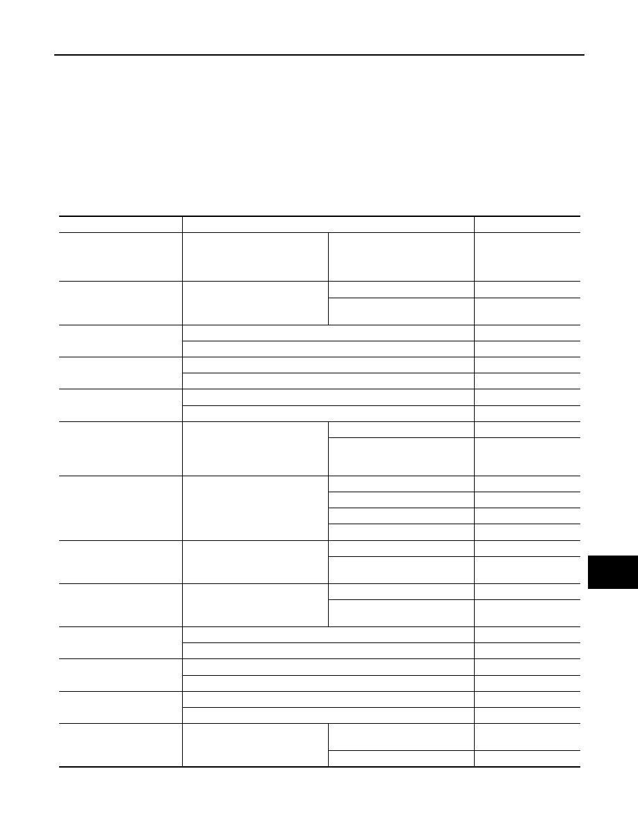
DTC
CONSULT display
description
DTC Detection Condition
Possible causes
B2099
IGN RELAY OFF
CIRC
The ignition relay OFF is detected for 1 second at ignition switch ON
(CPU monitors the status at the contact and excitation coil circuits of
the ignition relay inside it)
Ignition relay malfunction
(+)
(–)
Voltage
(Approx)
IPDM E/R
Connector
Terminal
E10
27
Ground
0 V

PCS
B2099 IGNITION RELAY OFF STUCK
PCS-19
< DTC/CIRCUIT DIAGNOSIS >
[IPDM E/R]
C
D
E
F
G
H
I
J
K
L
B
A
O
P
N
YES
>> Replace IPDM E/R. Refer to
PCS-37, "Removal and Installation"
.
NO
>> GO TO 3.
3.
CHECK BATTERY VOLTAGE
Check battery voltage.
Which is the measurement result?
More than 12.4 V>>GO TO 4.
Less than 12.4 V>>Perform battery inspection. Refer to
4.
CHECK INTERMITTENT INCIDENT
GI-44, "Intermittent Incident"
.
>> INSPECTION END

PCS-20
< DTC/CIRCUIT DIAGNOSIS >
[IPDM E/R]
POWER SUPPLY AND GROUND CIRCUIT
POWER SUPPLY AND GROUND CIRCUIT
Diagnosis Procedure
INFOID:0000000009722632
1.
CHECK FUSES AND FUSIBLE LINK
Check that the following IPDM E/R fuses or fusible links are not blown.
Is the fuse fusing?
YES
>> Replace the blown fuse or fusible link after repairing the affected circuit if a fuse or fusible link is
blown.
NO
>> GO TO 2.
2.
CHECK POWER SUPPLY CIRCUIT
1.
Turn the ignition switch OFF.
2.
Disconnect IPDM E/R connector.
3.
Check voltage between IPDM E/R harness connector and the ground.
Is the measurement value normal?
YES
>> GO TO 3.
NO
>> Repair the harness or connector.
3.
CHECK GROUND CIRCUIT
Check continuity between IPDM E/R harness connectors and the ground.
Does continuity exist?
YES
>> INSPECTION END
NO
>> Repair the harness or connector.
Signal name
Fuses and fusible link No.
Battery power supply
E
50
51
Terminals
Voltage
(Approx.)
(+)
(
−
)
IPDM E/R
Connector
Terminal
Ground
E9
1
Battery voltage
IPDM E/R
Ground
Continuity
Connector
Terminal
E10
12
Existed
E11
41
PCS
IPDM E/R (INTELLIGENT POWER DISTRIBUTION MODULE ENGINE ROOM)
PCS-21
< ECU DIAGNOSIS INFORMATION >
[IPDM E/R]
C
D
E
F
G
H
I
J
K
L
B
A
O
P
N
ECU DIAGNOSIS INFORMATION
IPDM E/R (INTELLIGENT POWER DISTRIBUTION MODULE ENGINE
ROOM)
Reference Value
INFOID:0000000009722633
VALUES ON THE DIAGNOSIS TOOL
NOTE:
The following table includes information (items) inapplicable to this vehicle. For information (items) applicable
to this vehicle, refer to CONSULT display items.
Monitor Item
Condition
Value/Status
MOTOR FAN REQ
Engine idle speed
Changes depending on engine
coolant temperature, air conditioner
operation status, vehicle speed,
etc.
1/2/3/4
AC COMP REQ
Engine running
A/C switch OFF
Off
A/C switch ON
(Compressor is operating)
On
TAIL&CLR REQ
Lighting switch OFF
Off
Lighting switch 1ST, 2ND, HI or AUTO (Light is illuminated)
On
HL LO REQ
Lighting switch OFF
Off
Lighting switch 2ND HI or AUTO (Light is illuminated)
On
HL HI REQ
Lighting switch OFF
Off
Lighting switch HI
On
FR FOG REQ
Lighting switch 2ND or
AUTO (Light is illuminated)
Front fog lamp switch OFF
Off
• Front fog lamp switch ON
• Daytime running light activated
(Only for Canada)
On
FR WIP REQ
Ignition switch ON
Front wiper switch OFF
Stop
Front wiper switch INT
1LOW
Front wiper switch LO
Low
Front wiper switch HI
Hi
WIP AUTO STOP
Ignition switch ON
Front wiper stop position
STOP P
Any position other than front wiper
stop position
ACT P
WIP PROT
Ignition switch ON
Front wiper operates normally
Off
Front wiper stops at fail-safe opera-
tion
BLOCK
IGN RLY1 -REQ
Ignition switch OFF or ACC
Off
Ignition switch ON
On
IGN RLY
Ignition switch OFF or ACC
Off
Ignition switch ON
On
PUSH SW
Release the push-button ignition switch
Off
Press the push-button ignition switch
On
INTER/NP SW
Ignition switch ON
Selector lever in any position other
than P or N
Off
Selector lever in P or N position
On
Нет комментариевНе стесняйтесь поделиться с нами вашим ценным мнением.
Текст