Nissan Murano. Manual — part 1063

PCS-14
< SYSTEM DESCRIPTION >
[IPDM E/R]
DIAGNOSIS SYSTEM (IPDM E/R)
EXTERNAL LAMPS
Off
OFF
TAIL
Operates the tail lamp relay.
Lo
Operates the headlamp low relay.
Hi
Operates the headlamp low relay and ON/OFF the headlamp high relay at 1 sec-
ond intervals.
Fog
Operates the front fog lamp relay.
Test item
Operation
Description

PCS
U1000 CAN COMM CIRCUIT
PCS-15
< DTC/CIRCUIT DIAGNOSIS >
[IPDM E/R]
C
D
E
F
G
H
I
J
K
L
B
A
O
P
N
DTC/CIRCUIT DIAGNOSIS
U1000 CAN COMM CIRCUIT
Description
INFOID:0000000009722623
CAN (Controller Area Network) is a serial communication line for real time applications. It is an on-vehicle mul-
tiplex communication line with high data communication speed and excellent error detection ability. Modern
vehicle is equipped with many electronic control unit, and each control unit shares information and links with
other control units during operation (not independent). In CAN communication, control units are connected
with 2 communication lines (CAN-H line, CAN-L line) allowing a high rate of information transmission with less
wiring. Each control unit transmits/receives data but selectively reads required data only.
CAN Communication Signal Chart. Refer to
LAN-29, "CAN Communication Signal Chart"
DTC Logic
INFOID:0000000009722624
DTC DETECTION LOGIC
Diagnosis Procedure
INFOID:0000000009722625
1.
PERFORM SELF DIAGNOSTIC
1.
Turn the ignition switch ON and wait for 2 seconds or more.
2.
Check “Self Diagnostic Result” of IPDM E/R.
Is DTC “U1000” displayed?
YES
>> Refer to
LAN-18, "Trouble Diagnosis Flow Chart"
NO
>> Refer to
GI-44, "Intermittent Incident"
.
DTC
CONSULT display de-
scription
DTC Detection Condition
Possible cause
U1000
CAN COMM CIRCUIT
When IPDM E/R cannot communicate CAN
communication signal continuously for 2
seconds or more
CAN communication system
PCS-16
< DTC/CIRCUIT DIAGNOSIS >
[IPDM E/R]
B2098 IGNITION RELAY ON STUCK
B2098 IGNITION RELAY ON STUCK
Description
INFOID:0000000009722626
• IPDM E/R operates the ignition relay when it receives an ignition switch ON signal from BCM via CAN com-
munication.
• Turn the ignition relay OFF by pressing the push-button ignition switch once when the vehicle speed is 4 km/
h (2.5 MPH) or less.
• Turn the ignition relay OFF with the following operation when the vehicle speed is more than 4 km/h (2.5
MPH) or when an abnormal condition occurs in CAN communication from the combination meter (Emer-
gency OFF)
- Press and hold the push-button ignition switch for 2 seconds or more.
- Press the push-button ignition switch 3 times within 1.5 seconds.
NOTE:
The ignition relay does not turn ON for 3 seconds after emergency OFF even if the push-button ignition switch
is pressed.
DTC Logic
INFOID:0000000009722627
DTC DETECTION LOGIC
DTC CONFIRMATION PROCEDURE
1.
PERFORM SELF DIAGNOSIS
1.
Turn the ignition switch ON.
2.
Turn ignition switch OFF and wait 1 second or more.
3.
Check DTC in “Self Diagnostic Result” mode of “IPDM E/R” using CONSULT.
Is DTC detected?
YES
>> Refer to
.
NO
>> INSPECTION END
Diagnosis Procedure
INFOID:0000000009722628
1.
CHECK SELF DIAGNOSTIC RESULT
Check DTC using CONSULT.
What is the display history of DTC “B2098”?
“CRNT”>> GO TO 2.
“PAST” >> GO TO 5.
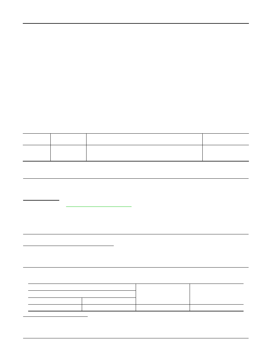
2.
CHECK IGNITION RELAY CONTROL CIRCUIT VOLTAGE 1
1.
Turn ignition switch ON
2.
Check voltage between IPDM E/R harness connector and ground.
Is the inspection result normal?
YES
>> GO TO 4.
NO
>> GO TO 3.
3.
CHECK IGNITION RELAY CONTROL CIRCUIT VOLTAGE 2
DTC
CONSULT display
description
DTC Detection Condition
Possible causes
B2098
IGN RELAY ON
CIRC
The ignition relay ON is detected for 1 second at ignition switch OFF
(CPU monitors the status at the contact and excitation coil circuits of
the ignition relay inside it)
Ignition relay malfunction
(+)
(–)
Voltage
(Approx.)
IPDM E/R
Connector
Terminal
E10
27
Ground
0 V
PCS
B2098 IGNITION RELAY ON STUCK
PCS-17
< DTC/CIRCUIT DIAGNOSIS >
[IPDM E/R]
C
D
E
F
G
H
I
J
K
L
B
A
O
P
N
1.
Disconnect IPDM E/R connector.
2.
Turn ignition switch ON
3.
Check voltage between IPDM E/R harness connector and ground.
Is the inspection result normal?
YES
>> Replace IPDM E/R. Refer to
PCS-37, "Removal and Installation"
.
NO
>> Check the harness of the ignition relay control circuit for a short to power.
4.
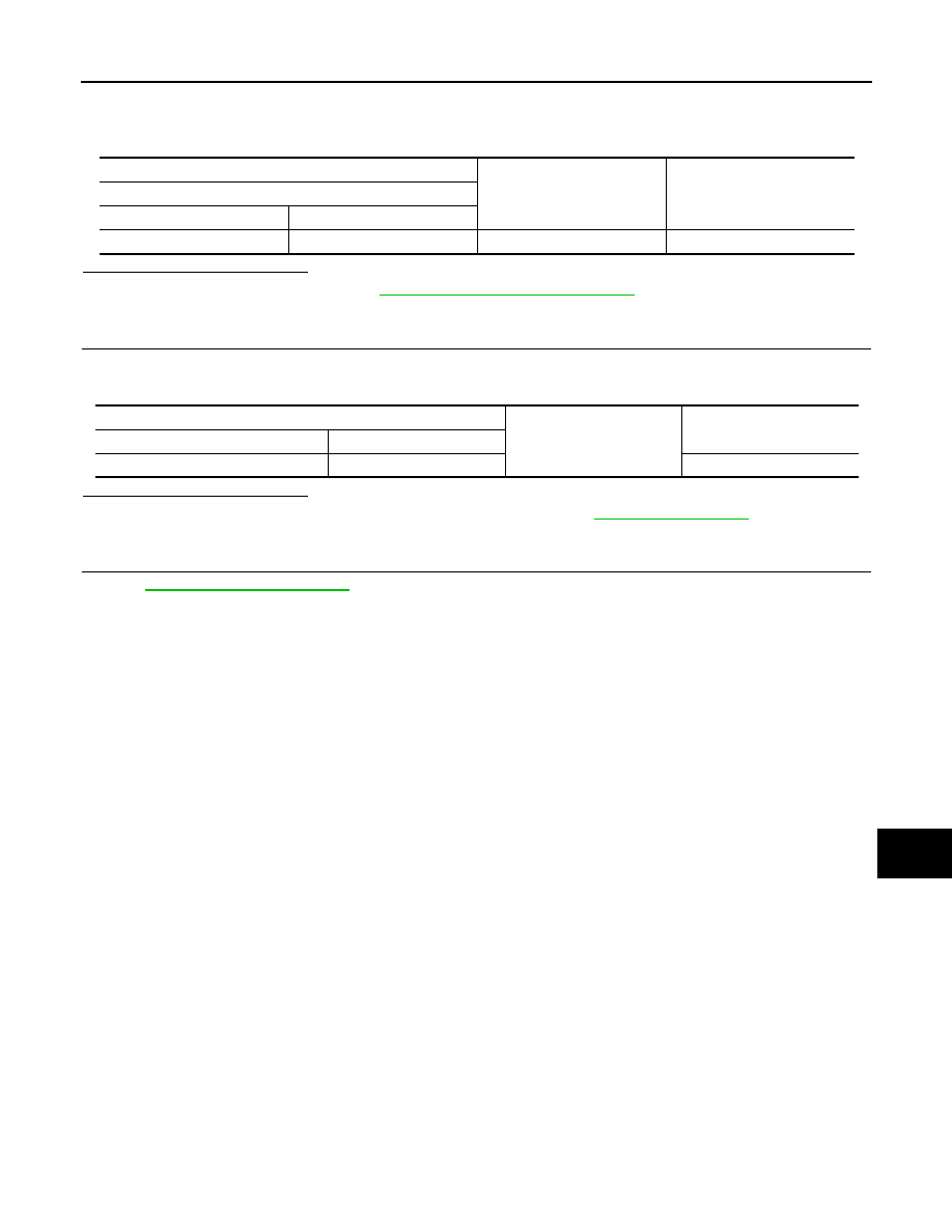
CHECK IGNITION RELAY CONTROL CIRCUIT
1.
Disconnect IPDM E/R connector.
2.
Check continuity between IPDM E/R harness connector and ground.
Is the inspection result normal?
YES
>> Perform the diagnosis procedure for DTC B260A. Refer to
NO
>> Repair or replace harness.
5.
CHECK INTERMITTENT INCIDENT
GI-44, "Intermittent Incident"
.
>> INSPECTION END
(+)
(–)
Voltage
(Approx.)
IPDM E/R
Connector
Terminal
E10
27
Ground
0 V
IPDM E/R
Ground
Continuity
Connector
Terminal
E10
27
Not existed
Нет комментариевНе стесняйтесь поделиться с нами вашим ценным мнением.
Текст