Nissan Murano. Manual — part 609
EM-10
< PRECAUTION >
PRECAUTIONS
If turning the steering wheel is required with the battery disconnected or discharged, follow the operation pro-
cedure below before starting the repair operation.
OPERATION PROCEDURE
1.
Connect both battery cables.
NOTE:
Supply power using jumper cables if battery is discharged.
2.
Turn the ignition switch to ACC position.
(At this time, the steering lock will be released.)
3.
Disconnect both battery cables. The steering lock will remain released with both battery cables discon-
nected and the steering wheel can be turned.
4.
Perform the necessary repair operation.
5.
When the repair work is completed, re-connect both battery cables. With the brake pedal released, turn
the ignition switch from ACC position to ON position, then to LOCK position. (The steering wheel will lock
when the ignition switch is turned to LOCK position.)
6.
Perform self-diagnosis check of all control units using CONSULT.
FOR MEXICO : Precautions For Engine Service
INFOID:0000000009717944
DISCONNECTING FUEL PIPING
• Before starting work, check no fire or spark producing items are in the work area.
• Release fuel pressure before disconnecting and disassembly.
• After disconnecting pipes, plug openings to stop fuel leakage.
DRAINING ENGINE COOLANT
Drain engine coolant and engine oil when the engine is cooled.
INSPECTION, REPAIR AND REPLACEMENT
Before repairing or replacing, thoroughly inspect parts. Inspect new replacement parts in the same way, and
replace if necessary.
REMOVAL AND DISASSEMBLY
• When instructed to use SST, use specified tools. Always be careful to work safely, avoid forceful or unin-
structed operations.
• Exercise maximum care to avoid damage to mating or sliding surfaces.
• Dowel pins are used for several parts alignment. When replacing and reassembling parts with dowel pins,
check that dowel pins are installed in the original position.
• Must cover openings of engine system with a tape or equivalent, to seal out foreign materials.
• Mark and arrange disassembly parts in an organized way for easy troubleshooting and reassembly.
• When loosening nuts and bolts, as a basic rule, start with the one furthest outside, then the one diagonally
opposite, and so on. If the order of loosening is specified, do exactly as specified. Power tools may be used
in the step.
ASSEMBLY AND INSTALLATION
• Use torque wrench to tighten bolts or nuts to specification.
• When tightening nuts and bolts, as a basic rule, equally tighten in several different steps starting with the
ones in center, then ones on inside and outside diagonally in this order. If the order of tightening is specified,
do exactly as specified.
• Replace with new gasket, packing, oil seal or O-ring.
• Thoroughly wash, clean, and air-blow each part. Carefully check engine oil or engine coolant passages for
any restriction and blockage.
• Avoid damaging sliding or mating surfaces. Completely remove foreign materials such as cloth lint or dust.
Before assembly, oil sliding surfaces well.
• After disassembling, or exposing any internal engine parts, change engine oil and replace oil filter with a new
one.
• Release air within route when refilling after draining engine coolant.
• After repairing, start the engine and increase engine speed to check engine coolant, fuel, engine oil, and
exhaust gases for leakage.
PRECAUTIONS
EM-11
< PRECAUTION >
C
D
E
F
G
H
I
J
K
L
M
A
EM
N
P
O
FOR MEXICO : Precaution for Angle Tightening
INFOID:0000000009717945
• Use the angle wrench [SST: KV10112100 (BT8653-A)] for the final tightening of the following engine parts:
- Cylinder head bolts
- Main bearing cap bolts
- Connecting rod cap bolts
- Crankshaft pulley bolt (No the angle wrench is required as bolt flange is provided with notches for angle
tightening)
• Never use a torque value for final tightening.
• The torque value for these parts are for a preliminary step.
• Ensure thread and seat surfaces are clean and coated with engine oil.
FOR MEXICO : Precaution for Liquid Gasket
INFOID:0000000009717946
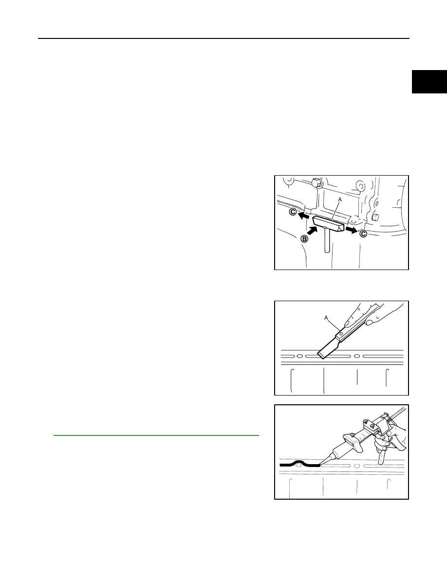
REMOVAL OF LIQUID GASKET SEALING
• After removing mounting nuts and bolts, separate the mating sur-
face using the seal cutter [SST: KV10111100 (J-37228)] (A) and
remove old liquid gasket sealing.
CAUTION:
Be careful not to damage the mating surfaces.
• Tap (B) the seal cutter [SST: KV10111100 (J-37228)] to insert it,
and then slide (C) it by tapping on the side as shown in the figure.
• In areas where the seal cutter [SST: KV10111100 (J-37228)] is dif-
ficult to use, use a plastic hammer to lightly tap the parts, to
remove it.
CAUTION:
If for some unavoidable reason tool such as a screwdriver is
used, be careful not to damage the mating surfaces.
LIQUID GASKET APPLICATION PROCEDURE
1.
Using a scraper (A), remove old liquid gasket adhering to the
gasket application surface and the mating surface.
• Remove liquid gasket completely from the groove of the gas-
ket application surface, mounting bolts, and bolt holes.
2.
Wipe the liquid gasket application surface and the mating sur-
face with white gasoline (lighting and heating use) to remove
adhering moisture, grease and foreign materials.
3.
Attach liquid gasket tube to the tube presser (commercial ser-
vice tool).
Use Genuine RTV Silicone Sealant or equivalent. Refer to
GI-22, "Recommended Chemical Products and Sealants"
.
4.
Apply liquid gasket without breaks to the specified location with
the specified dimensions.
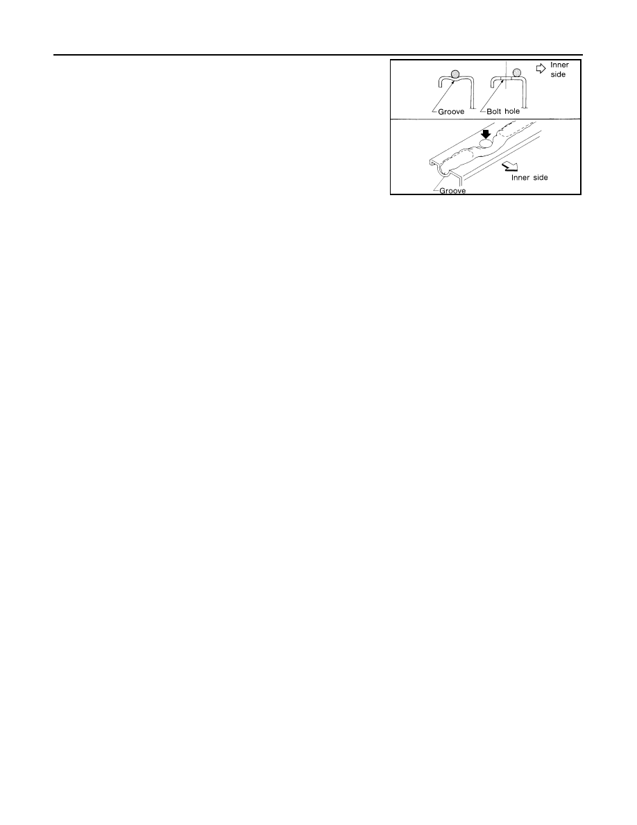
• If there is a groove for liquid gasket application, apply liquid
gasket to the groove.
JPBIA0052ZZ
JPBIA0053ZZ
EMA0622D
EM-12
< PRECAUTION >
PRECAUTIONS
• As for bolt holes, normally apply liquid gasket inside the holes.
Occasionally, it should be applied outside the holes. Check to
read the text of this manual.
• Within 5 minutes of liquid gasket application, install the mating
component.
• If liquid gasket protrudes, wipe it off immediately.
• Never retighten mounting bolts or nuts after the installation.
• After 30 minutes or more have passed from the installation, fill
engine oil and engine coolant.
CAUTION:
If there are specific instructions in this manual, observe
them.
SEM159F
PREPARATION
EM-13
< PREPARATION >
C
D
E
F
G
H
I
J
K
L
M
A
EM
N
P
O
PREPARATION
PREPARATION
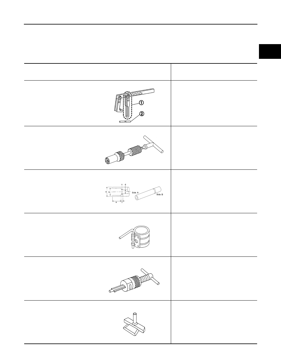
Special Service Tool
INFOID:0000000009717947
The actual shapes of Kent-Moore tools may differ from those of special service tools illustrated here.
Tool number
(Kent-Moore No.)
Tool name
Description
KV10116200
(J-26336-A)
Valve spring compressor
1. KV10115900
(J-26336-20)
Attachment
2. KV10109220
(
—
)
Adapter
Disassembling valve mechanism
Part (1) is a component of KV10116200 (J-
26336-A), but Part (2) is not so.
KV10107902
(J-38959)
Valve oil seal puller
Replacing valve oil seal
KV10115600
(J-38958)
Valve oil seal drift
Installing valve oil seal
Use side A.
a: 20 mm (0.79 in) dia.
b: 13 mm (0.51 in) dia.
c: 10.3 mm (0.406 in) dia.
d: 8 mm (0.31 in) dia.
e: 10.7 mm (0.421 in)
f: 5 mm (0.20 in)
EM03470000
(J-8037)
Piston ring compressor
Installing piston assembly into cylinder bore
ST16610001
(J-23907)
Pilot bushing puller
Removing pilot converter
KV10111100
(J-37228)
Seal cutter
Removing oil pan (lower and upper), front and
rear timing chain case, etc.
PBIC1650E
NT011
S-NT603
NT044
NT045
NT046
Нет комментариевНе стесняйтесь поделиться с нами вашим ценным мнением.
Текст