Nissan Murano. Manual — part 610
EM-14
< PREPARATION >
PREPARATION
Commercial Service Tool
INFOID:0000000009717948
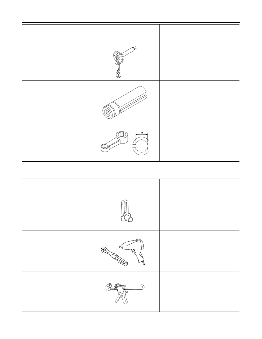
KV10112100
(BT8653-A)
Angle wrench
Tightening bolts for connecting rod bearing
cap, cylinder head, etc. in angle
KV10117100
(J-3647-A)
Heated oxygen sensor wrench
Loosening or tightening air fuel ratio sensor 1
For 22 mm (0.87 in) width hexagon nut
KV10114400
(J-38365)
Heated oxygen sensor wrench
Loosening or tightening heated oxygen sen-
sor 2
a: 22 mm (0.87 in)
Tool number
(Kent-Moore No.)
Tool name
Description
NT014
NT379
NT636
(Kent-Moore No.)
Tool name
Description
(J-45488)
Quick connector release
Removing fuel tube quick connectors in en-
gine room
(
—
)
Power tool
Loosening bolts and nuts
(
—
)
Tube presser
Pressing the tube of liquid gasket
PBIC0198E
PBIC0190E
NT052
PREPARATION
EM-15
< PREPARATION >
C
D
E
F
G
H
I
J
K
L
M
A
EM
N
P
O
(
—
)
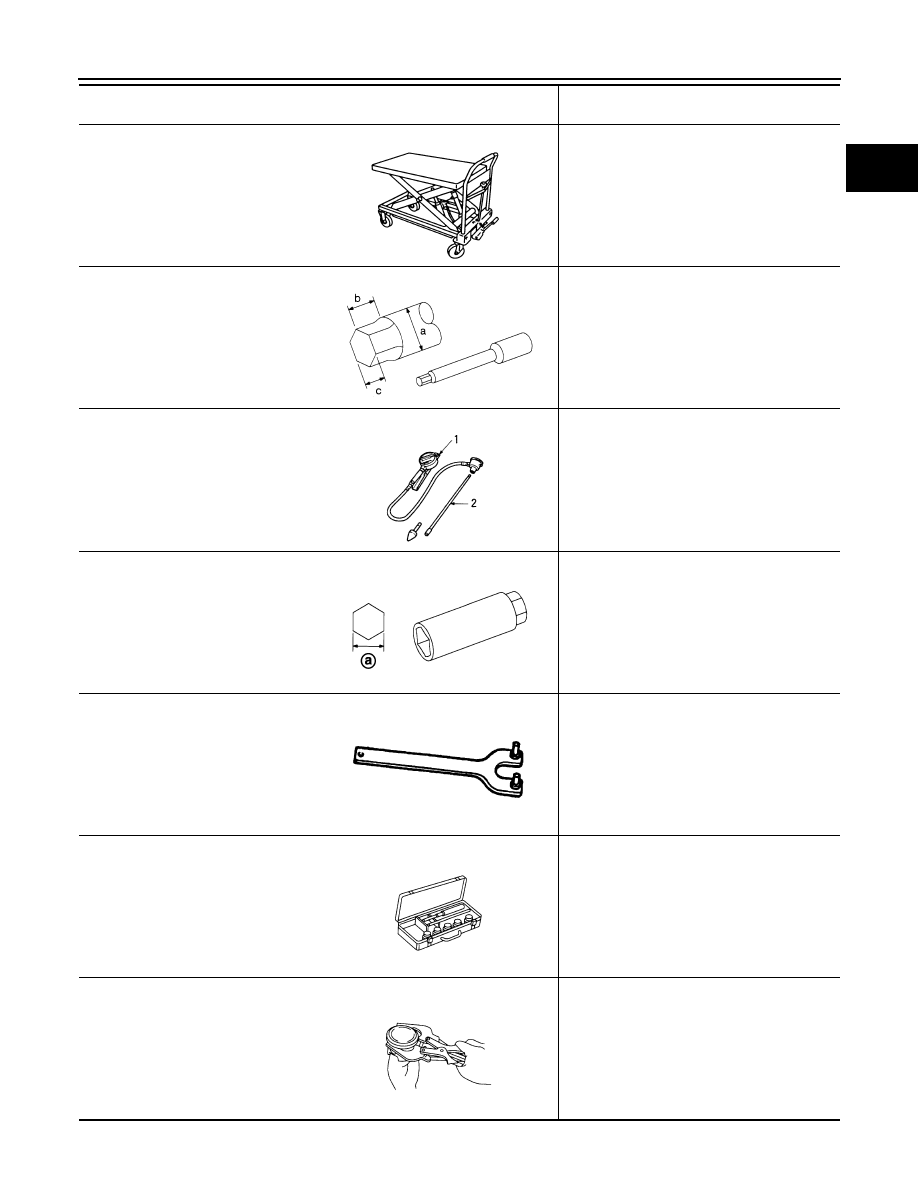
Manual lift table caddy
Removing and installing engine
(J-24239-01)
Cylinder head bolt wrench
Loosening and tightening cylinder head bolt,
and used with the angle wrench [SST:
KV10112100 (BT8653-A)]
a: 13 mm (0.51 in) dia.
b: 12 mm (0.47 in)
c: 10 mm (0.39 in)
(
—
)
1. Compression tester
2. Adapter
Checking compression pressure
(
—
)
Spark plug wrench
Removing and installing spark plug
a: 14 mm (0.55 in)
(
—
)
Pulley holder
Removing and installing crankshaft pulley
(
—
)
Valve seat cutter set
Finishing valve seat dimensions
(
—
)
Piston ring expander
Removing and installing piston ring
(Kent-Moore No.)
Tool name
Description
ZZA1210D
NT583
ZZA0008D
JPBIA0399ZZ
ZZA1010D
NT048
NT030
EM-16
< PREPARATION >
PREPARATION
(
—
)
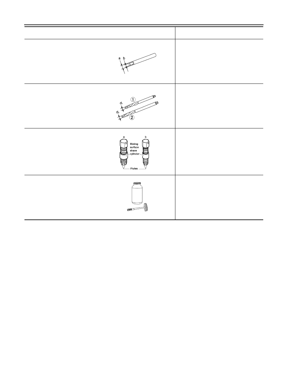
Valve guide drift
Removing and installing valve guide
Intake and Exhaust:
a: 9.5 mm (0.374 in) dia.
b: 5.5 mm (0.217 in) dia.
(
—
)
Valve guide reamer
(1): Reaming valve guide inner hole
(2): Reaming hole for oversize valve guide
Intake and Exhaust:
d
1
: 6.0 mm (0.236 in) dia.
d
2
: 10.2 mm (0.402 in) dia.
a: (J-43897-18)
b: (J-43897-12)
Oxygen sensor thread cleaner
Reconditioning the exhaust system threads
before installing a new air fuel ratio sensor and
heated oxygen sensor (Use with anti-seize lu-
bricant shown below.)
a: J-43897-18 [18 mm (0.71 in) dia.] for zir-
conia heated oxygen sensor and air fuel
ratio sensor
b: J-43897-12 [12 mm (0.47 in) dia.] for tita-
nia heated oxygen sensor
(
—
)
Anti-seize lubricant (Permatex 133AR
or equivalent meeting MIL specifica-
tion MIL-A-907)
Lubricating air fuel ratio sensor and oxygen
sensor threads cleaning tool when recondi-
tioning exhaust system threads
(Kent-Moore No.)
Tool name
Description
NT015
NT016
AEM488
AEM489
DRIVE BELT
EM-17
< PERIODIC MAINTENANCE >
C
D
E
F
G
H
I
J
K
L
M
A
EM
N
P
O
PERIODIC MAINTENANCE
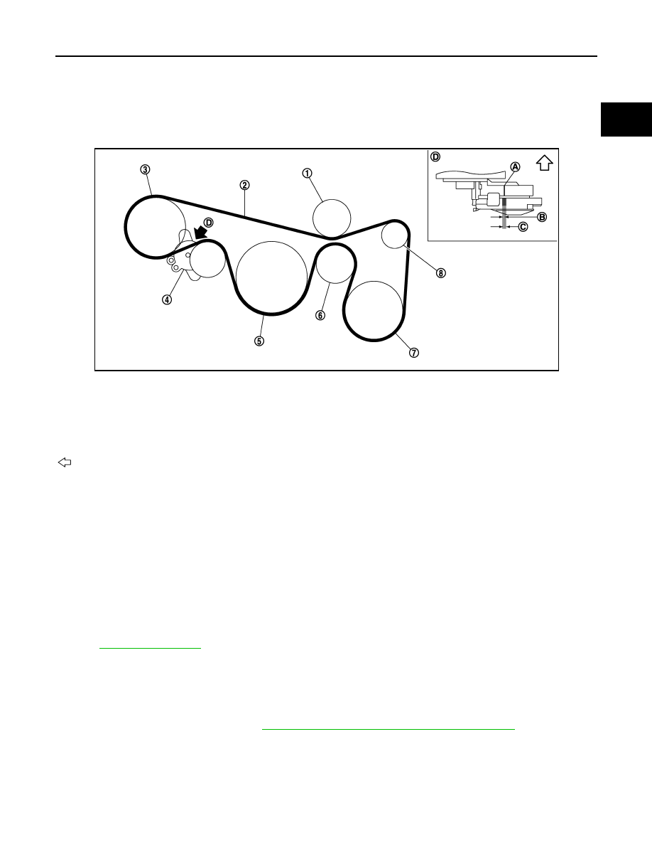
DRIVE BELT
Exploded View
INFOID:0000000009717949
Checking
INFOID:0000000009717950
WARNING:
Be sure to perform the this step when engine is stopped.
• Check that the indicator (A) of drive belt auto-tensioner is within the possible use range (C).
NOTE:
• Check the drive belt auto-tensioner indication when the engine is cold.
• When new drive belt is installed, the indicator should be within the range (B) in the figure.
• Visually check entire drive belt for wear, damage or cracks.
• If the indicator is out of the possible use range or belt is damaged, replace drive belt.
Tension Adjustment
INFOID:0000000009717951
.
Removal and Installation
INFOID:0000000009717952
REMOVAL
1.
Remove front wheel and tire (RH).
2.
Remove splash guard (RH). Refer to
EXT-26, "FENDER PROTECTOR : Exploded View"
.
JPBIA1625ZZ
1.
Idler pulley
2.
Drive belt
3.
Power steering oil pump
4.
Drive belt auto-tensioner
5.
Crankshaft pulley
6.
Idler pulley
7.
A/C compressor
8.
Alternator
A.
Indicator
B.
Range when new drive belt is installed
C.
Possible use range
D.
View D
: Engine front
Нет комментариевНе стесняйтесь поделиться с нами вашим ценным мнением.
Текст