Qashqai J11. Audio, Visual & Navigation System — part 4

AV
AUDIO SYSTEM
AV-49
< SYMPTOM DIAGNOSIS >
[AUDIO SYSTEM]
C
D
E
F
G
H
I
J
K
L
M
B
A
O
P
RELATED TO HANDS-FREE PHONE
• Before performing diagnosis, confirm that the cellular phone being used by the customer is compatible with
the vehicle.
• It is possible that a malfunction is occurring due to a version change of the phone even though the phone is
a compatible type. This can be confirmed by changing the cellular phone to another compatible type, and
check that it operates normally. It is important to determine whether the cause of the malfunction is the vehi-
cle or the cellular phone.
Check Compatibility
1.
Make sure the customer
′
s Bluetooth
®
related concern is understood.
2.
Verify the customer
′
s concern.
NOTE:
The customer
′
s phone may be required, depending upon their concern.
3.
Write down the customer
′
s phone brand, model and service provider.
NOTE:
It is necessary to know the service provider. On occasion, a given phone may be on the approved list with
one provider, but may not be on the approved list with other providers.
Noise is mixed with audio.
Noise comes out from all speakers.
Malfunction in audio unit.
Refer to
AV-15, "On Board Diagnosis Func-
.
Noise comes out only from a certain speak-
er (front tweeter LH, front tweeter RH, front
door speaker LH, front door speaker RH,
rear door speaker LH, rear door speaker
RH).
• Poor connector connection of speaker.
• Sound signal circuit malfunction between
audio unit and speaker.
Refer to:
-
(front
tweeter).
-
(front door
speaker).
-
(rear door
speaker).
• Malfunction in speaker.
• Poor Installation of speaker (e.g. back-
lash and looseness).
Refer to:
-
AV-55, "Removal and Installation"
tweeter).
-
AV-56, "Removal and Installation"
door speaker).
-
AV-57, "Removal and Installation"
door speaker).
• Malfunction in audio unit.
Refer to
.
Noise is mixed with radio only (when the ve-
hicle hits a bump or while driving over bad
roads)
Poor connector connection of antenna or
antenna feeder.
Refer to
Amp., Satellite Antenna and Antenna Feed-
er"
No radio reception or poor reception.
• Other audio sounds are normal.
• Any radio station cannot be received or
poor reception is caused even after mov-
ing to a service area with good reception
(e.g. a place with clear view and no ob-
stacles generating external noises).
• Antenna amp. ON signal circuit malfunc-
tion.
Refer to
• Poor connector connection of antenna or
antenna feeder.
Refer to
Amp., Satellite Antenna and Antenna
Feeder"
Buzz/rattle sound from speaker
The majority of buzz/rattle sounds are not
indicative of an issue with the speaker, usu-
ally something nearby the speaker is caus-
ing the buzz/rattle.
Refer to "SQUEAK AND RATTLE TROU-
BLE DIAGNOSIS" in the appropriate interi-
or trim section.
Symptoms
Check items
Probable malfunction location

AV-50
< SYMPTOM DIAGNOSIS >
[AUDIO SYSTEM]
AUDIO SYSTEM
4.
Perform diagnosis as per the following table.
Symptoms
Check items
Probable malfunction location
Does not recognize cellular phone connec-
tion (no connection is displayed on the dis-
play at the guide).
Repeat the registration of cellular phone.
Malfunction in audio unit.
Replace audio unit. Refer to
.
Hands-free phone cannot be established.
• Hands-free phone operation can be
made, but the communication cannot be
established.
• Hands-free phone operation can be per-
formed, however, voice between each
other cannot be heard during the conver-
sation.
The other party
′
s voice cannot be heard by
hands-free phone.
Check the “microphone speaker” in Inspec-
tion & Adjustment Mode if sound is heard.
Originating sound is not heard by the other
party with hands-free phone communica-
tion.
Sound operation function is normal.
Sound operation function does not work.
Microphone signal circuit malfunction.
Refer to
.
The system cannot be operated.
• The voice recognition can be controlled.
• Steering switch
′
s , ,
and
switch works, but
does not work.
Steering switch malfunction.
Replace steering switch. Refer to
Steering switch
′
s , , ,
and
switches do not work.
Steering switch signal circuit malfunction.
Refer to
All steering switches do not work.
Steering switch ground circuit malfunction.
Refer to

AV
NORMAL OPERATING CONDITION
AV-51
< SYMPTOM DIAGNOSIS >
[AUDIO SYSTEM]
C
D
E
F
G
H
I
J
K
L
M
B
A
O
P
NORMAL OPERATING CONDITION
Description
INFOID:0000000010502044
RELATED TO NOISE
The majority of the audio concerns are the result of outside causes (bad CD, electromagnetic interference,
etc.).
The following noise results from variations in field strength, such as fading noise and multi-path noise, or
external noise from trains and other sources. It is not a malfunction.
• Fading noise: This noise occurs because of variations in the field strength in a narrow range due to moun-
tains or buildings blocking the signal.
• Multi-path noise: This noise results from the waves sent directly from the broadcast station arriving at the
antenna at a different time from the waves which reflect off mountains or buildings.
The vehicle itself can be a source of noise if noise prevention parts or electrical equipment is malfunctioning.
Check if noise is caused and/or changed by engine speed, ignition switch turned to each position, and opera-
tion of each piece of electrical equipment, and determine the cause.
NOTE:
The source of the noise can be found easily by listening to the noise while removing the fuses of electrical
components, one by one.
Type of Noise and Possible Cause
RELATED TO HANDS-FREE PHONE
Occurrence condition
Possible cause
Occurs only when engine is ON.
A continuous growling noise occurs. The speed of
the noise varies with changes in the engine speed.
• Ignition components
The occurrence of the noise is linked with the operation of the fuel pump.
• Fuel pump condenser
Noise only occurs when various
electrical components are oper-
ating.
A cracking or snapping sound occurs with the op-
eration of various switches.
• Relay malfunction, audio unit malfunction
The noise occurs when various motors are operat-
ing.
• Motor case ground
• Motor
The noise occurs constantly, not just under certain conditions.
• Rear defogger coil malfunction
• Open circuit in printed heater
• Poor ground of antenna feeder line
A cracking or snapping sound occurs while the vehicle is being driven, especially when
it is vibrating excessively.
• Ground wire of body parts
• Ground due to improper part installation
• Wiring connections or a short circuit
Symptom
Cause and Counter measure
Does not recognize cellular phone connection (No connection is
displayed on the display at the guide).
Some Bluetooth
®
enabled cellular phones may not be recognized
by the in-vehicle phone module.
Refer to “RELATED TO HANDS-FREE PHONE (Check Compati-
bility)” in
Cannot use hands-free phone.
Customer will not be able to use a hands-free phone under the fol-
lowing conditions:
• The vehicle is outside of the telephone service area.
• The vehicle is in an area where it is difficult to receive radio
waves; such as in a tunnel, in an underground parking garage,
near a tall building or in a mountainous area.
• The cellular phone is locked to prevent it from being dialed.
NOTE:
While a cellular phone is connected through the Bluetooth
®
wire-
less connection, the battery power of the cellular phone may dis-
charge quicker than usual. The Bluetooth
®
Hands-Free Phone
System cannot charge cellular phones.

AV-52
< SYMPTOM DIAGNOSIS >
[AUDIO SYSTEM]
NORMAL OPERATING CONDITION
The other party
′
s voice cannot be heard by hands-free phone.
When the radio wave condition is not ideal or ambient sound is too
loud, it may be difficult to hear the other person
′
s voice during a
call.
Poor sound quality.
Do not place the cellular phone in an area surrounded by metal or
far away from the in-vehicle phone module to prevent tone quality
degradation and wireless connection disruption.
Symptom
Cause and Counter measure
AV
AUDIO UNIT
AV-53
< REMOVAL AND INSTALLATION >
[AUDIO SYSTEM]
C
D
E
F
G
H
I
J
K
L
M
B
A
O
P
REMOVAL AND INSTALLATION
AUDIO UNIT
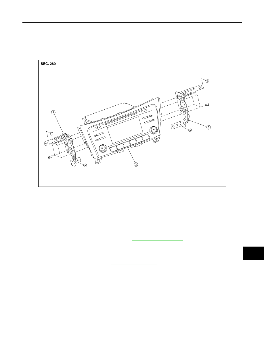
Exploded View
INFOID:0000000010502045
NOTE:
The following figures show the image of the inspection procedure. (Existing parts are not the same shape as
the parts in the figure.)
Removal and Installation
INFOID:0000000010502046
REMOVAL
1.
Disconnect the negative battery terminal. Refer to
2.
Remove A/C switch (AUTOMATIC AIR CONDITIONING) or front air control (MANUAL AIR CONDITION-
ING).
3.
Remove instrument finisher B. Refer to
4.
Remove instrument finisher E. Refer to
5.
Remove the audio unit screws, then pull out the audio unit.
6.
Disconnect the harness connectors from the audio unit and remove.
7.
Remove the audio unit bracket (LH/RH) screws and the audio unit brackets (LH/RH) (if necessary).
INSTALLATION
Installation is in the reverse order of removal.
1.
Audio unit bracket (LH)
2.
Audio unit
3.
Audio unit bracket (RH)
AWNIA3340ZZ

AV-54
< REMOVAL AND INSTALLATION >
[AUDIO SYSTEM]
STEERING SWITCHES
STEERING SWITCHES
Exploded View
INFOID:0000000010502047
Removal and Installation
INFOID:0000000010502048
REMOVAL
NOTE:
The steering switches are serviced as an assembly.
1.
Remove steering wheel. Refer to
2.
Release pawls on the steering wheel rear finisher and remove.
3.
Remove screws (A) and steering switches (1) from steering
wheel (2).
INSTALLATION
Installation is in the reverse order of removal.
1.
Steering wheel rear finisher
2.
Steering wheel
3.
Steering switches
Pawl
AWNIA3342ZZ
AWNIA3326ZZ
AV
FRONT TWEETER
AV-55
< REMOVAL AND INSTALLATION >
[AUDIO SYSTEM]
C
D
E
F
G
H
I
J
K
L
M
B
A
O
P
FRONT TWEETER
Removal and Installation
INFOID:0000000010502049
REMOVAL
1.
Remove defroster grille. Refer to
.
2.
Remove bolts and pull out the front tweeter.
3.
Disconnect the harness connector from the front tweeter and remove.
INSTALLATION
Installation is in the reverse order of removal.

AV-56
< REMOVAL AND INSTALLATION >
[AUDIO SYSTEM]
FRONT DOOR SPEAKER
FRONT DOOR SPEAKER
Exploded View
INFOID:0000000010502050
Removal and Installation
INFOID:0000000010502051
REMOVAL
1.
Remove front door finisher. Refer to
INT-12, "FRONT DOOR FINISHER : Exploded View"
2.
Remove front door speaker bolts, then pull out front door speaker.
3.
Disconnect the harness connector from front door speaker and remove.
INSTALLATION
Installation is in the reverse order of removal.
ALNIA1580ZZ
1.
Front door speaker

AV
REAR DOOR SPEAKER
AV-57
< REMOVAL AND INSTALLATION >
[AUDIO SYSTEM]
C
D
E
F
G
H
I
J
K
L
M
B
A
O
P
REAR DOOR SPEAKER
Exploded View
INFOID:0000000010502052
Removal and Installation
INFOID:0000000010502053
REMOVAL
1.
Remove rear door finisher. Refer to
INT-15, "REAR DOOR FINISHER : Exploded View"
2.
Remove rear door speaker bolts, then pull out rear door speaker.
3.
Disconnect the harness connector from the rear door speaker and remove.
INSTALLATION
Installation is in the reverse order of removal.
1.
Rear door speaker
ALNIA1581ZZ

AV-58
< REMOVAL AND INSTALLATION >
[AUDIO SYSTEM]
USB INTERFACE AND AUX IN JACK
USB INTERFACE AND AUX IN JACK
Removal and Installation
INFOID:0000000010502054
REMOVAL
1.
Remove center console. Refer to
2.
Release the pawls (A) on the back of USB interface and AUX in
jack (2).
INSTALLATION
Installation is in the reverse order of removal.
ALNIA1582ZZ
AV
MICROPHONE
AV-59
< REMOVAL AND INSTALLATION >
[AUDIO SYSTEM]
C
D
E
F
G
H
I
J
K
L
M
B
A
O
P
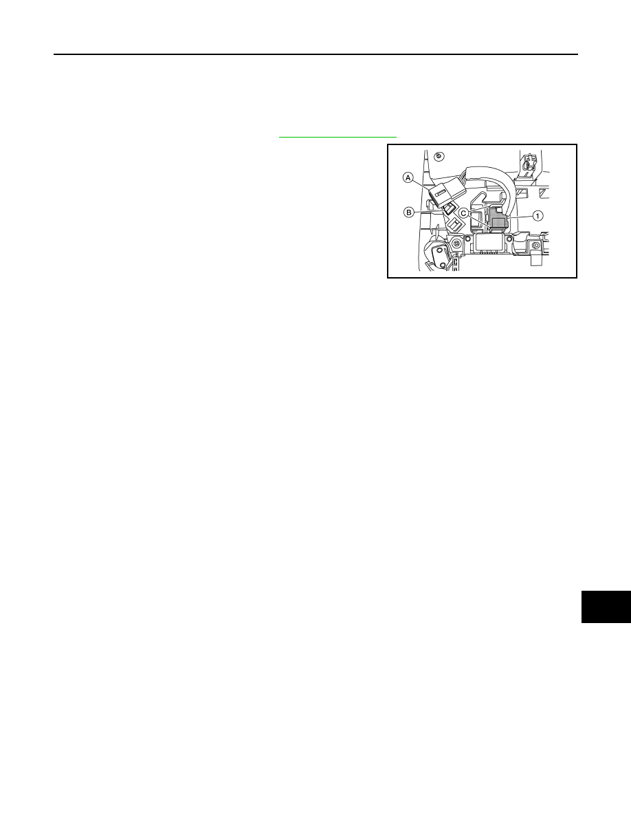
MICROPHONE
Removal and Installation
INFOID:0000000010502055
REMOVAL
1.
Remove the map lamp assembly. Refer to
2.
Release harness connector (A) by sliding rearward to remove
from the pawl (B).
3.
Release pawls (C) and remove the microphone (1) from the
front room/map lamp assembly.
NOTE:
The following figures show the image of the inspection proce-
dure. (Existing parts are not the same shape as the parts in the
figure.)
INSTALLATION
Installation is in the reverse order of removal.
ALNIA1583ZZ
AV-60
< REMOVAL AND INSTALLATION >
[AUDIO SYSTEM]
AUDIO ANTENNA
AUDIO ANTENNA
Removal and Installation
INFOID:0000000010502057
REMOVAL
1.
Remove the luggage side upper finisher (RH). Refer to
.
2.
Partially lower headlining (rear). Refer to
3.
Disconnect harness connectors from antenna feeder.
4.
Remove nut from audio antenna and remove.
INSTALLATION
Installation is in the reverse order of removal.
CAUTION:
If the audio antenna nut is not properly tightened, lower sensitivity of the antenna may be experi-
enced. If the nut is over tightened, this will deform the roof panel.
Audio antenna nut
: 6.5 N·m (0.66 kg-m, 58 in-lb)

AV
ANTENNA FEEDER
AV-61
< REMOVAL AND INSTALLATION >
[AUDIO SYSTEM]
C
D
E
F
G
H
I
J
K
L
M
B
A
O
P
ANTENNA FEEDER
Feeder Layout
INFOID:0000000010502285
ANTENNA FEEDER LAYOUT
1.
Antenna base (antenna amp. and
satellite antenna)
2.
Rod Antenna
3.
M394
4.
M385
E1NIA0073ZZ

AV-62
< PRECAUTION >
[DISPLAY AUDIO]
PRECAUTIONS
PRECAUTION
PRECAUTIONS
Precaution for Supplemental Restraint System (SRS) "AIR BAG" and "SEAT BELT
PRE-TENSIONER"
INFOID:0000000010519310
The Supplemental Restraint System such as “AIR BAG” and “SEAT BELT PRE-TENSIONER”, used along
with a front seat belt, helps to reduce the risk or severity of injury to the driver and front passenger for certain
types of collision. Information necessary to service the system safely is included in the “SRS AIR BAG” and
“SEAT BELT” of this Service Manual.
WARNING:
Always observe the following items for preventing accidental activation.
• To avoid rendering the SRS inoperative, which could increase the risk of personal injury or death in
the event of a collision that would result in air bag inflation, all maintenance must be performed by
an authorized NISSAN/INFINITI dealer.
• Improper maintenance, including incorrect removal and installation of the SRS, can lead to personal
injury caused by unintentional activation of the system. For removal of Spiral Cable and Air Bag
Module, see “SRS AIR BAG”.
• Never use electrical test equipment on any circuit related to the SRS unless instructed to in this Ser-
vice Manual. SRS wiring harnesses can be identified by yellow and/or orange harnesses or harness
connectors.
PRECAUTIONS WHEN USING POWER TOOLS (AIR OR ELECTRIC) AND HAMMERS
WARNING:
Always observe the following items for preventing accidental activation.
• When working near the Air Bag Diagnosis Sensor Unit or other Air Bag System sensors with the
ignition ON or engine running, never use air or electric power tools or strike near the sensor(s) with
a hammer. Heavy vibration could activate the sensor(s) and deploy the air bag(s), possibly causing
serious injury.
• When using air or electric power tools or hammers, always switch the ignition OFF, disconnect the
battery, and wait at least 3 minutes before performing any service.
Precaution for Harness Repair
INFOID:0000000010435589
AV COMMUNICATION SYSTEM
• Solder the repaired parts, and wrap with tape. [Frays of twisted line
must be within 110 mm (4.33 in).]
• Do not perform bypass wire connections for the repair parts. (The
spliced wire will become separated and the characteristics of
twisted line will be lost.)
PKIA0306E
PKIA0307E
AV
PRECAUTIONS
AV-63
< PRECAUTION >
[DISPLAY AUDIO]
C
D
E
F
G
H
I
J
K
L
M
B
A
O
P
Precaution for Work
INFOID:0000000010435590
• When removing or disassembling each component, be careful not to damage or deform it. If a component
may be subject to interference, be sure to protect it with a shop cloth.
• When removing (disengaging) components with a screwdriver or similar tool, be sure to wrap the component
with a shop cloth or vinyl tape to protect it.
• Protect the removed parts with a shop cloth and prevent them from being dropped.
• Replace a deformed or damaged clip.
• If a part is specified as a non-reusable part, always replace it with a new one.
• Be sure to tighten bolts and nuts securely to the specified torque.
• After installation is complete, be sure to check that each part works properly.
• Follow the steps below to clean components:
- Water soluble dirt:
• Dip a soft cloth into lukewarm water, wring the water out of the cloth and wipe the dirty area.
• Then rub with a soft, dry cloth.
- Oily dirt:
• Dip a soft cloth into lukewarm water with mild detergent (concentration: within 2 to 3%) and wipe the dirty
area.
• Then dip a cloth into fresh water, wring the water out of the cloth and wipe the detergent off.
• Then rub with a soft, dry cloth.
- Do not use organic solvent such as thinner, benzene, alcohol or gasoline.
- For genuine leather seats, use a genuine leather seat cleaner.

AV-64
< PREPARATION >
[DISPLAY AUDIO]
PREPARATION
PREPARATION
PREPARATION
Special Service Tool
INFOID:0000000010435591
The actual shape of the tools may differ from those illustrated here.
Commercial Service Tools
INFOID:0000000010435592
Tool number
(TechMate No.)
Tool name
Description
—
(J-46534)
Trim Tool Set
Removing trim components
AWJIA0483ZZ
Tool name
Description
Power tool
Loosening nuts, screws and bolts
PIIB1407E
Нет комментариевНе стесняйтесь поделиться с нами вашим ценным мнением.
Текст