Qashqai J11. Audio, Visual & Navigation System — part 2

AV
DIAGNOSIS SYSTEM (AUDIO UNIT)
AV-17
< SYSTEM DESCRIPTION >
[AUDIO SYSTEM]
C
D
E
F
G
H
I
J
K
L
M
B
A
O
P
2.
Select each switch on the Confirmation/Adjustment screen to
display the relevant trouble diagnosis screen. Press the BACK
switch to return to the initial Confirmation/Adjustment screen.
Display Diagnosis
Vehicle Signals
A comparison check can be made of each actual vehicle signal and
the signals recognized by the system.
Speaker Test
AWNIA3343ZZ
AWNIA2632GB
AWNIA3344ZZ

AV-18
< SYSTEM DESCRIPTION >
[AUDIO SYSTEM]
DIAGNOSIS SYSTEM (AUDIO UNIT)
Select Speaker Test to display the Speaker Diagnosis screen. Press
Start to generate a test tone in a speaker. Press Start again to gener-
ate a test tone in the next speaker. Press End to stop the test tones.
Error History
The self diagnosis results are judged depending on whether any error occurs from when Self Diagnosis is
selected until the self diagnosis results are displayed.
However, the diagnosis results are judged normal if an error has occurred before the ignition switch is turned
ON and then no error has occurred until the self diagnosis start. Check the Error Record to detect any error
that may have occurred before the self diagnosis start because of this situation.
The frequency of occurrence is displayed in a count up manner. The actual count up method differs depending
on the error item.
Count up method A
• The counter is set to 40 if an error occurs. 1 is subtracted from the counter if the condition is normal at a next
ignition ON cycle.
• The counter lower limit is 1. The counter can be reset (no error record display) with the Delete log switch.
Count up method B
• The counter increases by 1 if an error occurs when ignition switch is ON. The counter will not decrease even
if the condition is normal at the next ignition ON cycle.
• The counter upper limit is 50. Any counts exceeding 50 are ignored. The counter can be reset (no error
record display) with the Delete log switch.
Error item
Some error items may be displayed simultaneously according to the cause. If some error items are displayed
simultaneously, the detection of the cause can be performed by the combination of display items
AV COMM Diagnosis
AWNIA2634GB
Display type of occurrence
frequency
Error history display item
Count up method A
AV communication line, control unit (AV)
Count up method B
Other than the above
Error item
Description
Possible cause
CONTROL UNIT (AV)
AV communication circuit initial diagnosis
malfunction is detected.
Replace the audio unit if the malfunction
occurs constantly.
Refer to
AV-53, "Removal and Installation"
AV COMM CIRCUIT
When one of the following is detected:
• malfunction is detected in combination
meter power supply and ground circuits.
• malfunction is detected in AV communi-
cation circuits between audio unit and
combination meter.
• Combination meter power supply or
ground circuits.
Refer to
.
• AV communication circuits between au-
dio unit and combination meter.

AV
DIAGNOSIS SYSTEM (AUDIO UNIT)
AV-19
< SYSTEM DESCRIPTION >
[AUDIO SYSTEM]
C
D
E
F
G
H
I
J
K
L
M
B
A
O
P
• Displays the communication status between audio unit (master
unit) and each unit.
• The error counter displays OK if any malfunction was not detected
in the past and displays 0 if a malfunction is detected. It increases
by 1 if the condition is normal at the next ignition switch ON cycle.
The upper limit of the counter is 39.
• The error counter is erased if Reset is pressed.
NOTE:
“???” indicates UNKWN.
Delete Unit Connection Log
Deletes any unit connection records and error records from the
audio unit memory (clears the records of the unit that has been
removed).
Version Information
Displays audio unit software and hardware version numbers.
Initialize Settings
Deletes data stored from the audio unit.
Items
Status
(Current)
Counter
(Past)
C Rx(Meter-ITM)
OK / ???
OK / 0 – 39
C Tx(ITM-TW SW)
OK / ???
OK / 0 – 39
C Rx(STW SW-ITM)
OK / ???
OK / 0 – 39
AWNIA2636GB
AWNIA2637GB
AWNIA3346ZZ
JSNIA0155GB

AV-20
< ECU DIAGNOSIS INFORMATION >
[AUDIO SYSTEM]
AUDIO UNIT
ECU DIAGNOSIS INFORMATION
AUDIO UNIT
Reference Value
INFOID:0000000010505193
TERMINAL LAYOUT
PHYSICAL VALUES
AWNIA3347ZZ
Terminal
(Wire color)
Description
Condition
Reference value
(Approx.)
+
–
Signal name
Input/
Output
Ignition
switch
Operation
2
(L)
3
(V)
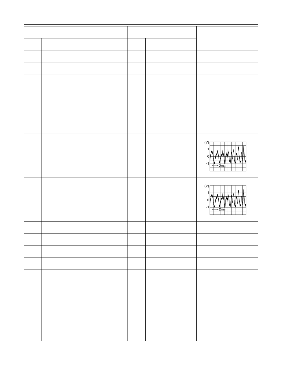
Sound signal front door
speaker and front tweeter
LH
Output
ON
Sound output
4
(W)
5
(Y)
Sound signal rear door
speaker LH
Output
ON
Sound output
7
(LG)
Ground
Ignition power supply
Input
ON
—
Battery voltage
9
(BR)
8
(R)
Illumination control signal
Input
ON
Headlamps ON
Battery voltage
11
(G)
12
(R)
Sound signal front door
speaker and front tweeter
RH
Output
ON
Sound output
SKIB3609E
SKIB3609E
SKIB3609E

AV
AUDIO UNIT
AV-21
< ECU DIAGNOSIS INFORMATION >
[AUDIO SYSTEM]
C
D
E
F
G
H
I
J
K
L
M
B
A
O
P
13
(LG)
14
(GR)
Sound signal rear door
speaker RH
Output
ON
Sound output
17
(P)
Ground
Dongle / AUDIO LINK
—
—
—
—
18
(P)
Ground
Vehicle speed signal
Input
ON
When vehicle speed is ap-
prox. 40 km/h (25 MPH)
19
(L)
Ground
Battery power supply
Input
OFF
—
Battery voltage
20
(B)
Ground
Ground
—
ON
—
0 V
27
(W)
Ground
ACC power supply
Input
ON
—
Battery voltage
31
(SB)
—
CAN H
—
—
—
—
32
(LG)
—
CAN L
—
—
—
—
33
(B)
Ground
Camera ground
—
ON
—
0 V
34
(R)
Ground
Camera power supply
Output
ON
Camera image displayed
6.0 V
Except for above
0 V
34
(R)
44
(GR)
Camera image signal
Input
ON
Camera image displayed
35
(W)
Ground
Camera detection
—
ON
—
0 V
37
(W)
39
(Shield)
Microphone signal
Input
ON
While speaking into micro-
phone.
38
(BG)
—
MIC VCC
Input
ON
—
—
Terminal
(Wire color)
Description
Condition
Reference value
(Approx.)
+
–
Signal name
Input/
Output
Ignition
switch
Operation
SKIB3609E
JSNIA0012GB
SKIB2251J
SKIB3609E
AV-22
< ECU DIAGNOSIS INFORMATION >
[AUDIO SYSTEM]
AUDIO UNIT
40
(LG)
—
AV communication (L)
Input/
Output
—
—
—
41
(SB)
—
AV communication (H)
Input/
Output
—
—
—
42
(LG)
—
AV communication (L)
Input/
Output
—
—
—
43
(SB)
—
AV communication (H)
Input/
Output
—
—
—
45
(B)
—
EQ1
—
—
—
—
50
(G)
Ground
Reverse signal
Input
ON
Selector lever in R (re-
verse)
Battery voltage
Selector lever in any posi-
tion other than R (reverse)
0 V
53
(B)
Ground
AUX jack audio signal LH
Input
ON
Received audio signal
(AUX input)
54
(R)
Ground
AUX jack audio signal RH
Input
ON
Received audio signal
(AUX input)
55
(W)
Ground
AUX ground
—
ON
—
0V
56
(Shield)
—
AUX signal shield
—
—
—
—
129
(G)
—
USB ground
—
—
—
—
130
(R)
—
USB D
−
signal
—
—
—
—
131
(W)
—
V BUS signal
—
—
—
—
133
(Shield)
—
USB shield
—
—
—
—
132
(L)
—
USB D+ signal
—
—
—
—
150
—
Ground
FN sub signal
Input
ON
Audio unit ON, XM select-
ed.
5.0 V
152
—
Ground
Antenna amp. ON signal
Output
ON
Audio unit ON, FM-AM se-
lected.
Battery voltage
151
—
Ground
AM/FM antenna signal
Input
ON
Audio unit ON, FM-AM se-
lected.
5.0 V
Terminal
(Wire color)
Description
Condition
Reference value
(Approx.)
+
–
Signal name
Input/
Output
Ignition
switch
Operation
SKIB3609E
SKIB3609E

AV
AUDIO SYSTEM
AV-23
< WIRING DIAGRAM >
[AUDIO SYSTEM]
C
D
E
F
G
H
I
J
K
L
M
B
A
O
P
WIRING DIAGRAM
AUDIO SYSTEM
Wiring Diagram
INFOID:0000000010502032
JRNWD1346GB

AV-24
< WIRING DIAGRAM >
[AUDIO SYSTEM]
AUDIO SYSTEM
JRNWD1347GB

AV
AUDIO SYSTEM
AV-25
< WIRING DIAGRAM >
[AUDIO SYSTEM]
C
D
E
F
G
H
I
J
K
L
M
B
A
O
P
JRNWD1348GB

AV-26
< WIRING DIAGRAM >
[AUDIO SYSTEM]
AUDIO SYSTEM
JRNWD1424GB

AV
AUDIO SYSTEM
AV-27
< WIRING DIAGRAM >
[AUDIO SYSTEM]
C
D
E
F
G
H
I
J
K
L
M
B
A
O
P
JRNWD1425GB

AV-28
< WIRING DIAGRAM >
[AUDIO SYSTEM]
AUDIO SYSTEM
JRNWD1426GB

AV
AUDIO SYSTEM
AV-29
< WIRING DIAGRAM >
[AUDIO SYSTEM]
C
D
E
F
G
H
I
J
K
L
M
B
A
O
P
JRNWD1427GB

AV-30
< WIRING DIAGRAM >
[AUDIO SYSTEM]
AUDIO SYSTEM
JRNWD1428GB

AV
AUDIO SYSTEM
AV-31
< WIRING DIAGRAM >
[AUDIO SYSTEM]
C
D
E
F
G
H
I
J
K
L
M
B
A
O
P
JRNWD1429GB

AV-32
< WIRING DIAGRAM >
[AUDIO SYSTEM]
AUDIO SYSTEM
JRNWD1430GB
Нет комментариевНе стесняйтесь поделиться с нами вашим ценным мнением.
Текст