Nissan Qashqai J11. Manual — part 24

TURBOCHARGER
EM-35
< REMOVAL AND INSTALLATION >
[HRA2DDT]
C
D
E
F
G
H
I
J
K
L
M
A
EM
N
P
O
• Replace the exhaust manifold and turbocharger assembly when any malfunction is found after unit
inspections specified in the table below.
• If no malfunction is found after the unit inspections, judge that the turbocharger body has no non-stan-
dard conditions. Check the other parts again.
INSPECTION AFTER REMOVAL
Turbocharger
Inspection Location
Result
Symptoms likely to occur when the results shown on
the left exist.
Oil leakage
Smoke
Noise
Poor pow-
er
Poor ac-
celeration
Turbine wheel
Wet with oil.
C
A
C
C
Carbon deposits observed.
C
A
B
B
“Rubs against” housing.
C
B
A
B
Vane is bent or broken.
A
A
Compressor wheel
Inside of intake port is badly stained
with oil.
B
B
“Rubs against” housing.
C
B
A
B
Vane is bent or broken.
A
A
Check both turbine and compres-
sor rotor shaft end play.
Heavy feel or catching when turned by
hand.
C
C
B
Cannot be turned by hand.
A
Excessively loose bearing.
C
C
B
C
Rotor shaft, oil return port (Check
inside using penlight.)
Carbon or sludge deposits in oil drain
port.
C
A
C
C
Boost control valve actuator oper-
ation (using a handy pump)
• Does not operate smoothly when air
pressure is gradually applied.
• Stroke amount is not compliance
with the air pressure.
A
A:
Highly possible.
B:
Possible.
C:
May exist.
EM-36
< REMOVAL AND INSTALLATION >
[HRA2DDT]
TURBOCHARGER
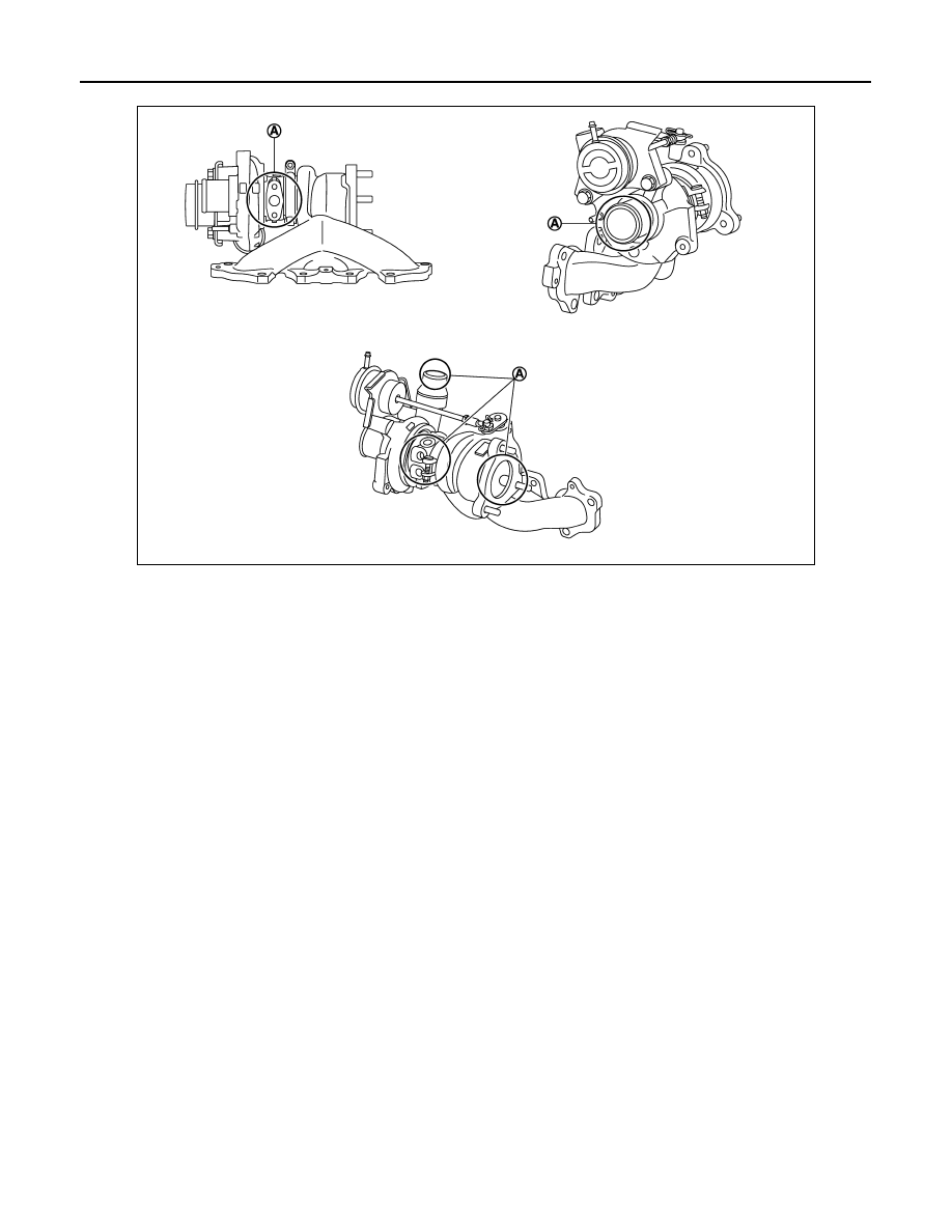
Turbocharger
CAUTION:
When the compressor wheel, turbine wheel or rotor shaft is damaged, remove all the fragments and
foreign matter left in the following passages in order to prevent a secondary failure:
INSPECTION AFTER INSTALLATION
Start engine and raise engine speed to check no exhaust emission leaks.
E1BIA1029ZZ
A.
Check for leakage
Suction side
: Between turbocharger and charge air cooler
Exhaust side
: Between turbocharger and outlet duct
EXHAUST MANIFOLD
EM-37
< REMOVAL AND INSTALLATION >
[HRA2DDT]
C
D
E
F
G
H
I
J
K
L
M
A
EM
N
P
O
EXHAUST MANIFOLD
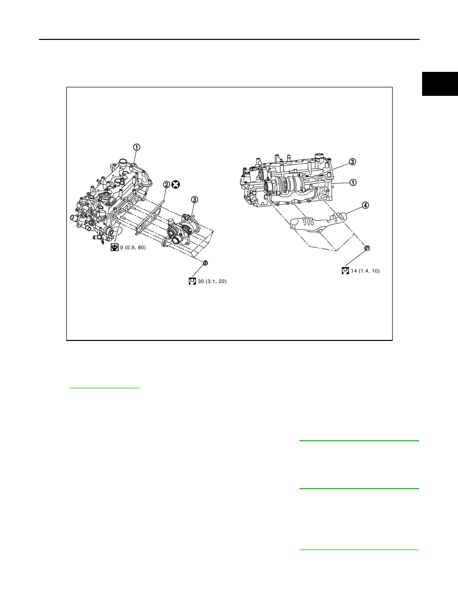
Exploded View
INFOID:0000000010282217
Removal and Installation
INFOID:0000000010282218
REMOVAL
NOTE:
• Exhaust manifold and turbocharger are assembled in one part. Refer to
EM-33, "Removal and Installation"
for removal.
INSTALLATION
NOTE:
• Exhaust manifold and turbocharger are assembled in one part. Refer to
EM-33, "Removal and Installation"
for installation.
Inspection
INFOID:0000000010282219
INSPECTION AFTER REMOVAL
NOTE:
• Exhaust manifold and turbocharger are assembled in one part. Refer to
EM-33, "Removal and Installation"
for inspection.
E1BIA1010GB
1.
Cylinder head
2.
Exhaust manifold gasket
3.
Exhaust manifold and turbocharg-
er assembly
4.
Exhaust manifold heat insulator

EM-38
< REMOVAL AND INSTALLATION >
[HRA2DDT]
HIGH PRESSURE FUEL PUMP AND FUEL HOSE
HIGH PRESSURE FUEL PUMP AND FUEL HOSE
Exploded View
INFOID:0000000010287264
CAUTION:
Never remove or disassemble parts unless instructed as shown in the figure.
for symbol marks in the figure.
Removal and Installation
INFOID:0000000010287265
REMOVAL
WARNING:
• Be sure to read
when working on the high pressure fuel system.
• Put a “CAUTION: FLAMMABLE” sign in the workshop.
• Be sure to work in a well ventilated area and furnish workshop with a CO
2
fire extinguisher.
• Never smoke while servicing fuel system. Keep open flames and sparks away from the work area.
• To avoid the danger of being scalded, never drain engine coolant when engine is hot.
1.
Remove electric blow off valve. Refer to
EM-27, "Removal and Installation"
.
2.
Release fuel pressure.
3.
Disconnect fuel feed hose quick connector with the following procedure. Disconnect fuel feed hose from
high pressure fuel pump.
1.
High pressure fuel pump
2.
High pressure fuel pipe
3.
High pressure fuel rail
4.
High pressure fuel pump O-ring
5.
High pressure fuel pump lifter
E1BIA1220GB
Нет комментариевНе стесняйтесь поделиться с нами вашим ценным мнением.
Текст