Nissan Qashqai J11. Manual — part 23
CATALYST
EM-31
< REMOVAL AND INSTALLATION >
[HRA2DDT]
C
D
E
F
G
H
I
J
K
L
M
A
EM
N
P
O
CATALYST
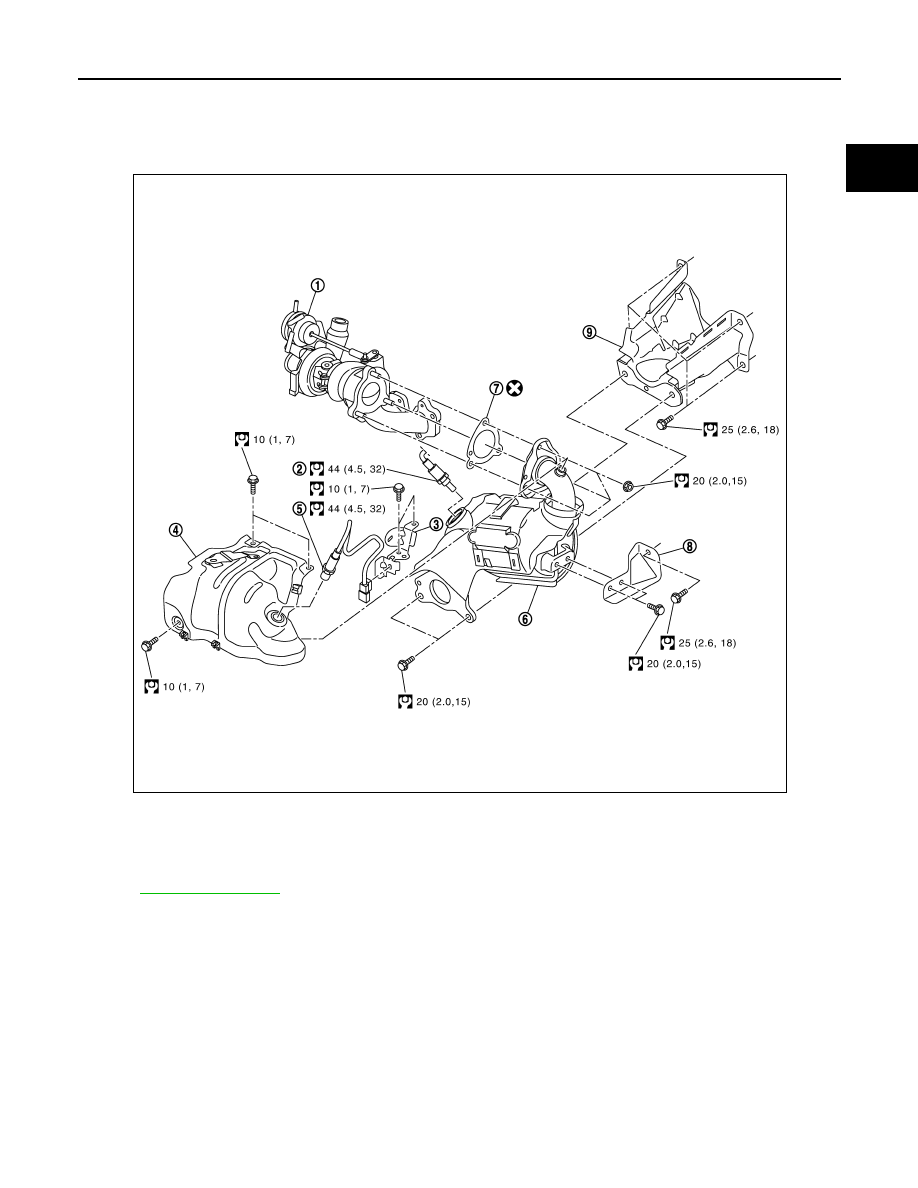
Exploded View
INFOID:0000000010287257
for symbol marks in the figure.
Removal and Installation
INFOID:0000000010287258
REMOVAL
1.
Remove engine undercover.
2.
Remove A/F sensor 1.
• Using heated oxygen sensor wrench [SST: KV10117100], remove A/F sensor 1.
CAUTION:
Handle A/F sensor 1 carefully and avoid impacts.
3.
Remove A/F sensor 2.
• Using heated oxygen sensor wrench [SST: KV10117100], remove A/F sensor 1.
CAUTION:
Handle A/F sensor 1 carefully and avoid impacts.
E1BIA1023GB
1.
Turbocharger
2.
A/F sensor 2
3.
A/F sensor 1 harness bracket
4.
Catalyst converter heat shield
5.
A/F sensor 1
6.
Catalyst converter
7.
Gasket
8.
Catalyst converter side bracket
9.
Catalyst converter support bracket
EM-32
< REMOVAL AND INSTALLATION >
[HRA2DDT]
CATALYST
4.
Remove catalyst converter heat shield.
5.
Remove front tube. Refer to
.
6.
Remove nuts of catalyst converter turbocharger side.
7.
Remove catalyst converter side bracket.
8.
Remove catalyst converter.
9.
Remove catalyst converter gasket.
10. Remove catalyst converter support bracket.
INSTALLATION
1.
Install new gasket between turbocharger and catalyst.
2.
Note the following, and install in the reverse order of removal.
A/F sensor 1
A/F sensor 2
• Using heated oxygen sensor wrench [SST: KV10117100], install A/F sensors.
CAUTION:
Prevent rust preventives from adhering to the sensor body.
TURBOCHARGER
EM-33
< REMOVAL AND INSTALLATION >
[HRA2DDT]
C
D
E
F
G
H
I
J
K
L
M
A
EM
N
P
O
TURBOCHARGER
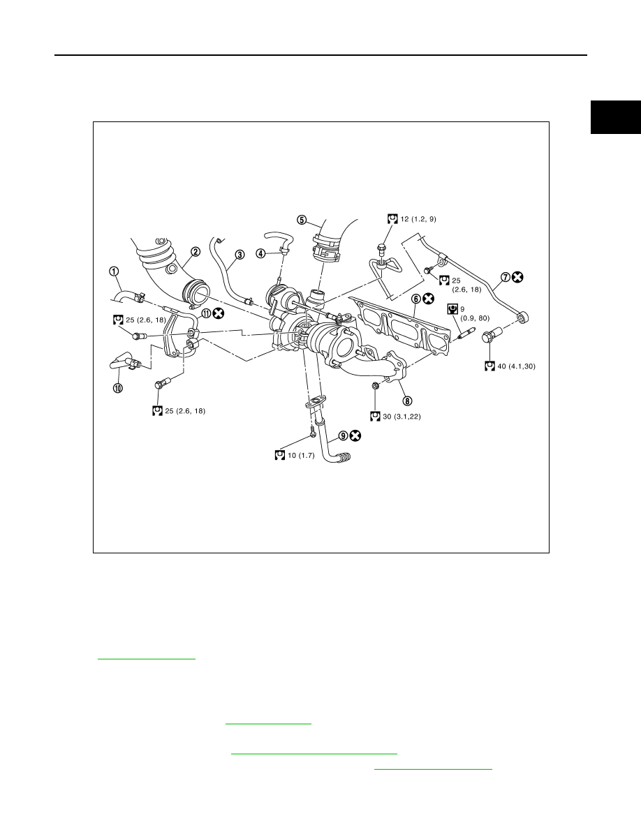
Exploded View
INFOID:0000000010287261
for symbol marks in the figure.
Removal and Installation
INFOID:0000000010287262
REMOVAL
1.
Drain engine coolant. Refer to
.
2.
Remove engine undercover.
3.
Remove air inlet hose. Refer to
EM-27, "Removal and Installation"
4.
Remove air cleaner filter unit assembly and air duct. Refer to
.
5.
Remove turbocharger heat shield.
1.
Water hose
2.
Air duct
3.
Exhaust gas pressure take off hose
4.
Wastegate hose
5.
Air inlet hose
6.
Exhaust manifold and turbocharger
assembly gasket
7.
Oil supply tube
8.
Exhaust manifold and turbocharger
assembly
9.
Oil return pipe
10. Water hose
11.
Turbocharger water pipe
E1BIA1024GB

EM-34
< REMOVAL AND INSTALLATION >
[HRA2DDT]
TURBOCHARGER
6.
Disconnect from turbocharger:
• Exhaust gas pressure take off hose.
• Wastegate control hose.
7.
Remove cowl top extension. Refer to
EXT-29, "Removal and Installation"
8.
Remove exhaust front tube. Refer to
9.
Remove catalyst converter and catalyst converter support bracket.Refer to
.
10. Remove turbocharger assembly as follows. Refer to
:
a.
Remove oil return tube and oil supply tube.
b.
Disconnect water hose from turbocharger.
c.
Remove mounting nuts of exhaust manifold in the reverse order
as shown in the figure.
d.
Remove turbocharger and exhaust manifold assembly.
e.
Remove exhaust manifold gasket.
CAUTION:
• Be careful not to impact or damage tubocharger when removing.
• Never disassemble the turbocharger body.
INSTALLATION
CAUTION:
Never reuse gasket, oil tube and water pipe.
Note the following, and Install in the reverse order of removal.
1.
Install turbocharger and exhaust manifold assembly as follows:
1.
Install new exhaust manifold gasket.
2.
Tighten exhaust manifold bolts in the numerical order as
shown in the figure.
3.
Torque tighten exhaust manifold bolts. Refer to
.
Inspection
INFOID:0000000010287263
INSPECTION PROCERDURE
Trouble Diagnosis of Turbocharger
Check items before trouble diagnosis
1.
Check that the engine oil level is between L (Low level) and H (High level) of the oil level gauge. [When
the engine oil amount is more then H (High level), the engine oil flows into the inlet duct through the blow-
by gas passage, and the turbocharger is misjudged failure.]
2.
Ask the customer if he/she always runs the vehicle in idle engine speed to cool the engine oil down after
driving.
E1BIA1011ZZ
E1BIA1011ZZ
Нет комментариевНе стесняйтесь поделиться с нами вашим ценным мнением.
Текст