Nissan Qashqai J11. Manual — part 963
C1116 STOP LAMP SWITCH
BRC-89
< DTC/CIRCUIT DIAGNOSIS >
[WITH ESP]
C
D
E
G
H
I
J
K
L
M
A
B
BRC
N
O
P
NO
>> Replace stop lamp switch.
Special Repair Requirement
INFOID:0000000010769622
1.
ADJUSTMENT OF STEERING ANGLE SENSOR NEUTRAL POSITION
Always perform the neutral position adjustment for the steering angle sensor, when replacing the ABS actua-
tor and electric unit (control unit). Refer to
>> END
BRC-90
< DTC/CIRCUIT DIAGNOSIS >
[WITH ESP]
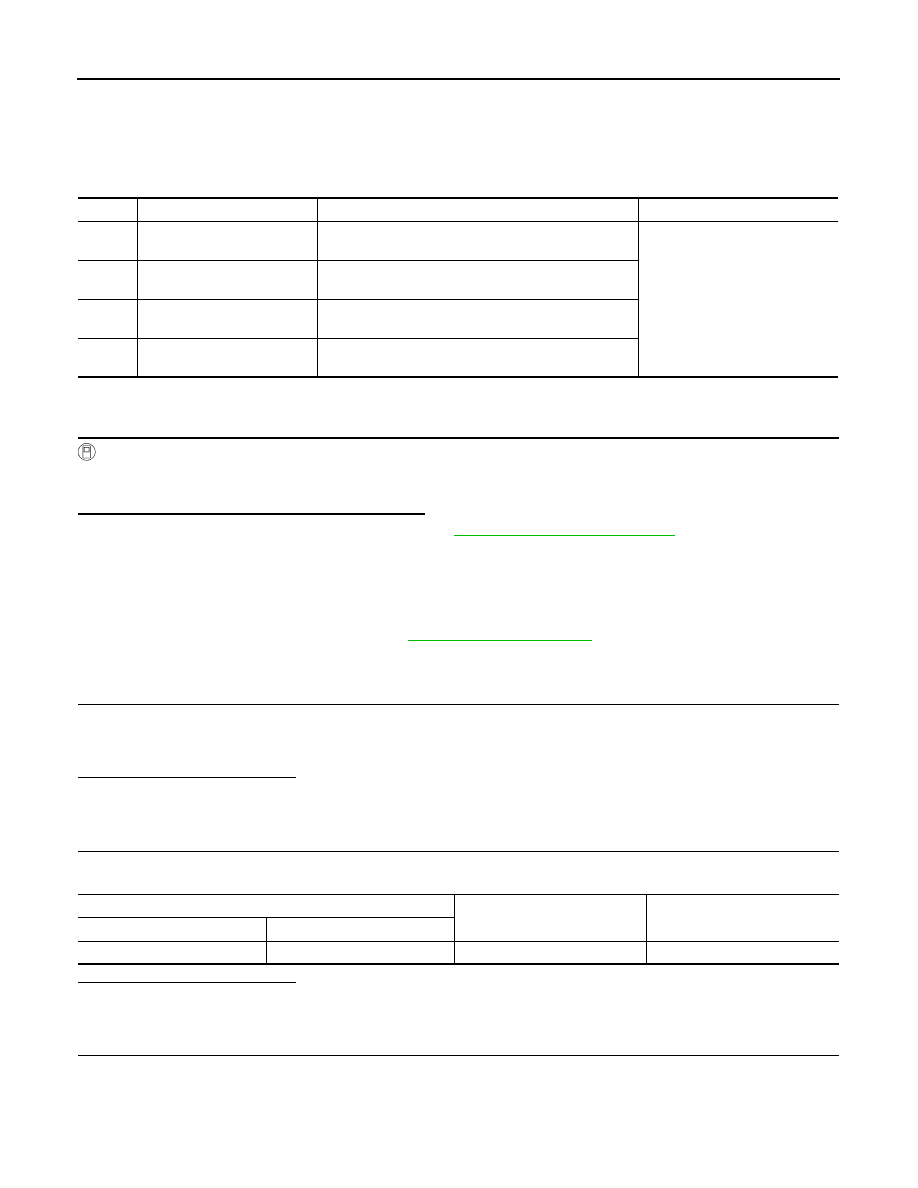
C1120, C1122, C1124, C1126 ABS IN VALVE SYSTEM
C1120, C1122, C1124, C1126 ABS IN VALVE SYSTEM
DTC Logic
INFOID:0000000010329827
DTC DETECTION LOGIC
DTC CONFIRMATION PROCEDURE
1.
CHECK SELF-DIAGNOSTIC RESULT
With CONSULT.
1.
Turn ignition switch OFF to ON.
2.
Perform self-diagnostic result.
Is DTC C1120, C1122, C1124 or C1126 detected?
YES
>> Proceed to diagnosis procedure. Refer to
.
NO
>> Inspection End.
Diagnosis Procedure
INFOID:0000000010329828
Regarding Wiring Diagram information, refer to
1.
CONNECTOR INSPECTION
1.
Turn ignition switch OFF.
2.
Disconnect ABS actuator and electric unit (control unit) connectors.
3.
Check connectors and terminals for deformation, disconnection, looseness or damage.
Is the inspection result normal?
YES
>> GO TO 2.
NO
>> Repair or replace as necessary.
2.
CHECK ABS ACTUATOR AND ELECTRIC UNIT (CONTROL UNIT) BATTERY POWER SUPPLY
Check voltage between ABS actuator and electric unit (control unit) connector E18 terminal 25 and ground.
Is the inspection result normal?
YES
>> GO TO 3.
NO
>> Repair or replace malfunctioning components.
3.
CHECK ABS ACTUATOR AND ELECTRIC UNIT (CONTROL UNIT) GROUND CIRCUIT
Check continuity between ABS actuator and electric unit (control unit) connector E18 terminals 13, 38 and
ground.
DTC
Display Item
Malfunction detected condition
Possible causes
C1120
FR LH IN ABS SOL
When a malfunction is detected in front LH ABS IN
valve.
• Harness or connector
• ABS actuator and electric unit
(control unit)
• Fusible link
• Battery power supply system
C1122
FR RH IN ABS SOL
When a malfunction is detected in front RH ABS IN
valve.
C1124
RR LH IN ABS SOL
When a malfunction is detected in rear LH ABS IN
valve.
C1126
RR RH IN ABS SOL
When a malfunction is detected in rear RH ABS IN
valve.
ABS actuator and electric unit (control unit)
—
Voltage
(Approx.)
Connector
Terminal
E18
25
Ground
Battery voltage

C1120, C1122, C1124, C1126 ABS IN VALVE SYSTEM
BRC-91
< DTC/CIRCUIT DIAGNOSIS >
[WITH ESP]
C
D
E
G
H
I
J
K
L
M
A
B
BRC
N
O
P
Is the inspection result normal?
YES
>> Replace ABS actuator and electric unit (control unit). Refer to
BRC-142, "Removal and Installa-
.
NO
>> Repair or replace malfunctioning components.
ABS actuator and electric unit (control unit)
—
Continuity
Connector
Terminal
E18
13
Ground
Yes
38

BRC-92
< DTC/CIRCUIT DIAGNOSIS >
[WITH ESP]
C1121, C1123, C1125, C1127 ABS OUT VALVE SYSTEM
C1121, C1123, C1125, C1127 ABS OUT VALVE SYSTEM
DTC Logic
INFOID:0000000010329829
DTC DETECTION LOGIC
DTC CONFIRMATION PROCEDURE
1.
CHECK SELF-DIAGNOSTIC RESULT
With CONSULT.
1.
Turn ignition switch OFF to ON.
2.
Perform self-diagnostic result.
Is DTC C1121, C1123, C1125 or C1127 detected?
YES
>> Proceed to diagnosis procedure. Refer to
.
NO
>> Inspection End.
Diagnosis Procedure
INFOID:0000000010329830
Regarding Wiring Diagram information, refer to
1.
CONNECTOR INSPECTION
1.
Turn ignition switch OFF.
2.
Disconnect ABS actuator and electric unit (control unit) connectors.
3.
Check connectors and terminals for deformation, disconnection, looseness or damage.
Is the inspection result normal?
YES
>> GO TO 2.
NO
>> Repair or replace as necessary.
2.
CHECK ABS ACTUATOR AND ELECTRIC UNIT (CONTROL UNIT) BATTERY POWER SUPPLY
Check voltage between ABS actuator and electric unit (control unit) connector E18 terminal 25 and ground.
Is the inspection result normal?
YES
>> GO TO 3.
NO
>> Repair or replace malfunctioning components.
3.
CHECK ABS ACTUATOR AND ELECTRIC UNIT (CONTROL UNIT) GROUND CIRCUIT
Check continuity between ABS actuator and electric unit (control unit) connector E18 terminals 13, 38 and
ground.
DTC
Display Item
Malfunction detected condition
Possible causes
C1121
FR LH OUT ABS SOL
When a malfunction is detected in front LH ABS OUT
valve.
• Harness or connector
• ABS actuator and electric unit
(control unit)
• Fusible link
• Battery power supply system
C1123
FR RH OUT ABS SOL
When a malfunction is detected in front RH ABS OUT
valve.
C1125
RR LH OUT ABS SOL
When a malfunction is detected in rear LH ABS OUT
valve.
C1127
RR RH OUT ABS SOL
When a malfunction is detected in rear RH ABS OUT
valve.
ABS actuator and electric unit (control unit)
—
Voltage
(Approx.)
Connector
Terminal
E18
25
Ground
Battery voltage
Нет комментариевНе стесняйтесь поделиться с нами вашим ценным мнением.
Текст