Nissan Qashqai J11. Manual — part 962

C1115 ABS SENSOR [ABNORMAL SIGNAL]
BRC-85
< DTC/CIRCUIT DIAGNOSIS >
[WITH ESP]
C
D
E
G
H
I
J
K
L
M
A
B
BRC
N
O
P
C1115 ABS SENSOR [ABNORMAL SIGNAL]
DTC Logic
INFOID:0000000010329825
DTC DETECTION LOGIC
DTC CONFIRMATION PROCEDURE
1.
CHECK SELF-DIAGNOSTIC RESULT
With
CONSULT.
1.
Start engine and drive vehicle at approximately 30 km/h (19 MPH) or more for approximately 1 minute.
2.
Perform self-diagnostic result.
Is DTC C1115 detected?
YES
>> Proceed to diagnosis procedure. Refer to
.
NO
>> Inspection End.
Diagnosis Procedure
INFOID:0000000010329826
Regarding Wiring Diagram information, refer to
CAUTION:
Do not check between wheel sensor terminals.
1.
CONNECTOR INSPECTION
1.
Disconnect ABS actuator and electric unit (control unit) connector E18 and wheel sensor connector of
wheel with DTC.
2.
Check terminals for deformation, disconnection, looseness or damage.
Is the inspection result normal?
YES
>> GO TO 2.
NO
>> Repair or replace as necessary.
2.
CHECK WHEEL SENSOR OUTPUT SIGNAL
1.
Connect ABS active wheel sensor tester (J-45741) to wheel sensor using appropriate adapter.
2.
Turn on the ABS active wheel sensor tester power switch.
NOTE:
The green POWER indicator should illuminate. If the POWER indicator does not illuminate, replace the
battery in the ABS active wheel sensor tester before proceeding.
3.
Spin the wheel of the vehicle by hand and observe the red SENSOR indicator on the ABS active wheel
sensor tester. The red SENSOR indicator should flash on and off to indicate an output signal.
NOTE:
If the red SENSOR indicator illuminates but does not flash, reverse the polarity of the tester leads and
retest.
Does the ABS active wheel sensor tester detect a signal?
YES
>> GO TO 3.
NO
>> Replace the wheel sensor. Refer to
BRC-138, "FRONT WHEEL SENSOR : Removal and Installa-
or
BRC-139, "REAR WHEEL SENSOR : Removal and Installation"
.
3.
CHECK TIRES
Check the inflation pressure, wear and size of each tire.
Is the inspection result normal?
DTC
Display Item
Malfunction detected condition
Possible causes
C1115
ABS SENSOR
[ABNORMAL SIGNAL]
When difference in wheel speed between any wheel
and others is detected while the vehicle is driven be-
cause of installation of tires other than specified.
• Harness or connector
• Wheel sensor
• Sensor rotor
• ABS actuator and electric unit
(control unit)
BRC-86
< DTC/CIRCUIT DIAGNOSIS >
[WITH ESP]
C1115 ABS SENSOR [ABNORMAL SIGNAL]
YES
>> GO TO 4.
NO
>> Adjust tire pressure, or replace tire(s).
4.
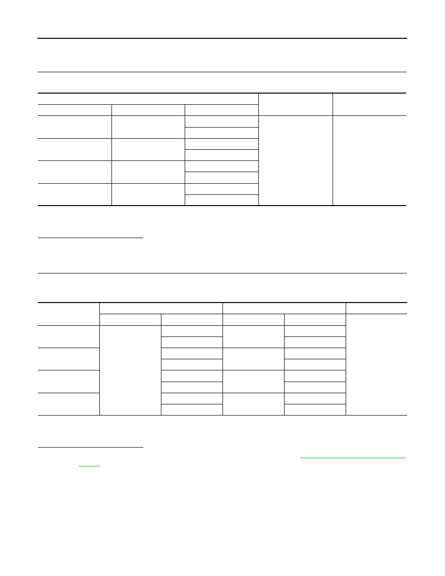
CHECK WIRING HARNESS FOR SHORT CIRCUIT
Check continuity between wheel sensor connector terminals and ground of wheel with DTC.
*1:With TC models
*2:With HT models
Is the inspection result normal?
YES
>> GO TO 5.
NO
>> Repair the circuit.
5.
CHECK WIRING HARNESS FOR OPEN CIRCUIT
Check continuity between ABS actuator and electric unit (control unit) connector E18 and wheel sensor con-
nector of wheel with DTC.
*1:With TC models
*2:With HT models
Is the inspection result normal?
YES
>> Replace the ABS actuator and electric unit (control unit). Refer to
.
NO
>> Repair the circuit.
Wheel Sensor
Ground
Continuity
Wheel
Connector
Terminal
Front LH
E53
1
—
No
2
Front RH
E54
3
4
Rear LH
B38
*1
B39
*2
5
6
Rear RH
B30
7
8
Wheel sensor
ABS actuator and electric unit (control unit)
Wheel sensor
Continuity
Connector
Terminal
Connector
Terminal
Yes
Front LH
E18
19
E53
1
8
2
Front RH
16
E54
3
4
4
Rear LH
31
B38
*1
B39
*2
5
18
6
Rear RH
17
B30
7
29
8

C1116 STOP LAMP SWITCH
BRC-87
< DTC/CIRCUIT DIAGNOSIS >
[WITH ESP]
C
D
E
G
H
I
J
K
L
M
A
B
BRC
N
O
P
C1116 STOP LAMP SWITCH
Description
INFOID:0000000010769618
The stop lamp switch transmits the stop lamp switch signal (ON/OFF) to the ABS actuator and electric unit
(control unit).
DTC Logic
INFOID:0000000010769619
DTC DETECTION LOGIC
DTC CONFIRMATION PROCEDURE
1.
CHECK SELF-DIAGNOSIS RESULTS
Check the self-diagnosis results.
Is above displayed on the self-diagnosis display?
YES
>> Proceed to diagnosis procedure. Refer to
.
NO
>> INSPECTION END
Diagnosis Procedure
INFOID:0000000010769620
INSPECTION PROCEDURE
1.
CHECK STOP LAMPS ILLUMINATE
Check stop lamps illuminate when brake pedal is pressed.
Is the inspection result normal?
YES
>> GO TO 2.
NO
>> Check stop lamp circuit.
2.
CHECK DATA MONITOR
Using “DATA MONITOR” check both pressure sensor signal and brake lamp switch signal.
Pressure sensor
Stop lamp switch
Is the inspection result normal?
YES
>> GO TO 3.
NO
>> Repair or replace malfunctioning parts.
3.
CHECK CONNECTOR
1.
Turn ignition switch OFF.
2.
Disconnect ABS actuator and electric unit (control unit) connector.
DTC
Display item
Malfunction detected condition
Possible cause
C1116
STOP LAMP SW
When stop lamp switch circuit is open.
• Harness or connector
• Stop lamp switch
• ABS actuator and electric unit
(control unit)
Self-diagnosis results
STOP LAMP SW
Condition
PRESS SEN (DATA MONITOR)
Brake pedal released
Approx. 3 bar
Brake pedal pressed
0 to 200 bar
Condition
STOP LAMP SW (DATA MONITOR)
Brake pedal released
OFF
Brake pedal pressed
ON

BRC-88
< DTC/CIRCUIT DIAGNOSIS >
[WITH ESP]
C1116 STOP LAMP SWITCH
3.
Disconnect stop lamp switch connector.
4.
Check terminal for deformation, disconnection, looseness, and so on. If any malfunction is found, repair or
replace terminal.
5.
Reconnect connectors securely.
6.
Start engine.
7.
Repeat pumping brake pedal carefully several times, and perform self-diagnosis. Refer to
Is any item indicated in the self-diagnosis display?
YES
>> GO TO 4.
NO
>> Poor connection of connector terminal. Replace or repair connector.
4.
CHECK STOP LAMP SWITCH
1.
Disconnect stop lamp switch connector.
2.
Check continuity between stop lamp switch connector terminals.
Is the inspection result normal?
YES
>> GO TO 5.
NO
>> Replace stop lamp switch.
5.
CHECK STOP LAMP SWITCH CIRCUIT
1.
Disconnect ABS actuator and electric unit (control unit) connector.
2.
Connect stop lamp switch connector.
3.
Check voltage between ABS actuator and electric unit (control unit) harness connector terminal and
ground.
Is the inspection result normal?
YES
>> Replace ABS actuator and electric unit (control unit).
NO
>> Repair or replace harness.
Component Inspection
INFOID:0000000010769621
1.
CHECK STOP LAMP SWITCH
1.
Turn ignition switch OFF.
2.
Disconnect stop lamp switch connector.
3.
Check continuity between stop lamp switch connector terminals.
Is the inspection result normal?
YES
>> INSPECTION END
Stop lamp switch
Condition
Continuity
Terminal
1
−
2
Release stop lamp switch
(When brake pedal is depressed.)
Existed
Push stop lamp switch
(When brake pedal is released.)
Not existed
ABS actuator and electric unit (control unit)
Condition
Voltage
Connector
Terminal
E36
20
Brake pedal is depressed
Battery voltage
Brake pedal is released
Approx. 0 V
Stop lamp switch
Condition
Continuity
Terminal
1
−
2
Release stop lamp switch
(When brake pedal is depressed.)
Existed
Push stop lamp switch
(When brake pedal is released.)
Not existed
Нет комментариевНе стесняйтесь поделиться с нами вашим ценным мнением.
Текст