
Chrysler Stratus Convertible. Manual — part 58
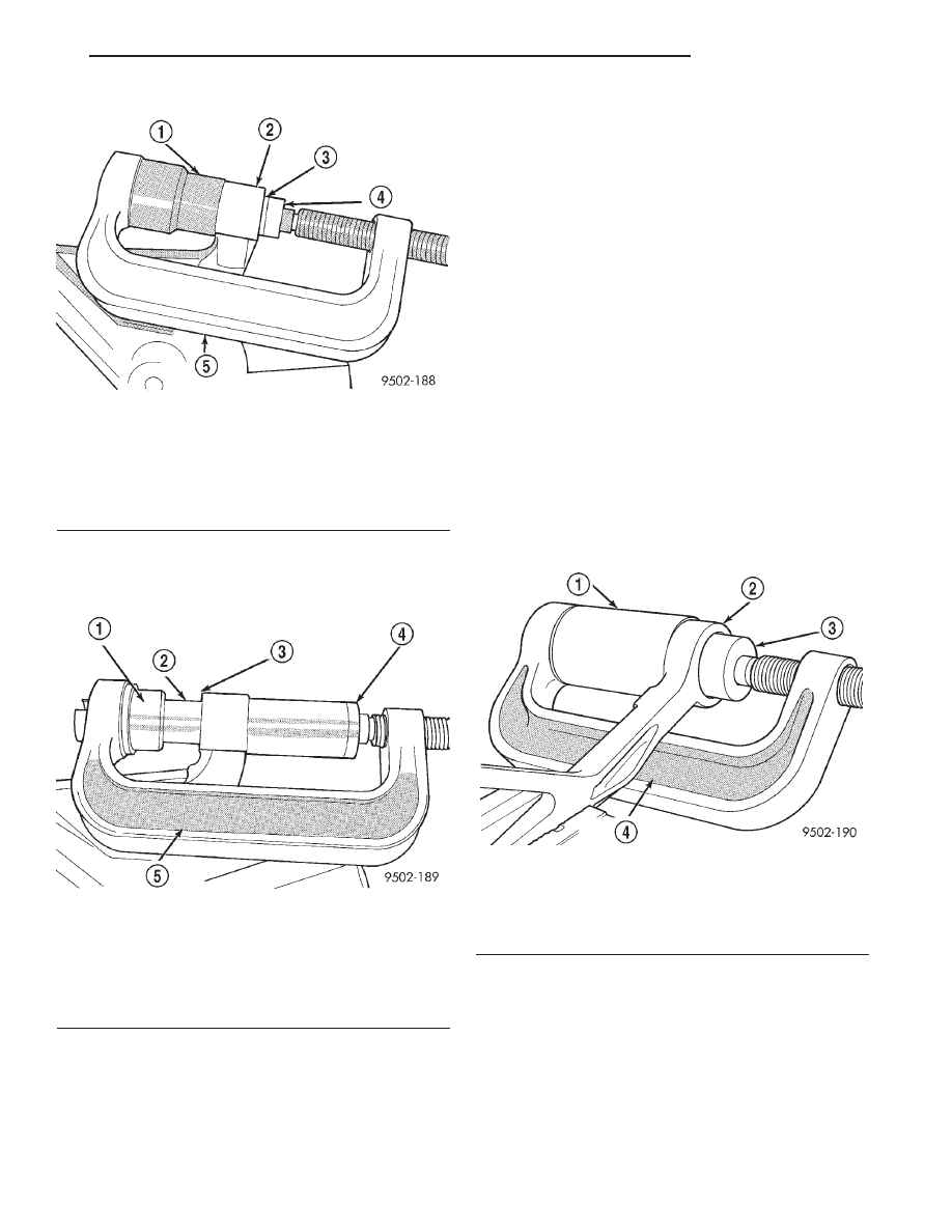
into lower control arm (Fig. 82). Be sure Special Tool
6758 is square on lower control arm and Special Tool
6876 is positioned correctly on isolator bushing.
(4) Tighten screw on Remover/Installer Special
Tool C-4212-F pressing front bushing into lower con-
trol arm. Continue pressing front bushing into lower
control arm until bushing is sitting flush on the
machined surface of the lower control arm. This will
correctly position front bushing in lower control arm.
(5) Install lower control arm assembly back on
vehicle. See Lower Control Arm Installation in this
section of the service manual for the required instal-
lation procedure.
LOWER CONTROL ARM REAR ISOLATOR
BUSHING
To perform removal and replacement of the lower
control arm isolator bushings, the lower control arm
must be removed from the vehicle.
DISASSEMBLY
(1) Remove lower control arm assembly from vehi-
cle. See Lower Control Arm Removal in this section
of the service manual for the required removal proce-
dure.
(2) Install Bushing Remover, Special Tool 6756 and
Bushing Receiver, Special Tool C-4366-2 on Special
Tool C-4212-F (Fig. 83).
(3) Install Special Tools assembled for removal of
the rear isolator bushing on the lower control arm.
Be sure Special Tool C-4366-2 is square on lower con-
trol arm and Special Tool 6756 is positioned correctly
on isolator bushing (Fig. 83).
(4) Tighten screw on Remover/Installer Special
Tool C-4212-F to press rear bushing out of lower con-
trol arm.
ASSEMBLY
(1) Start rear bushing into lower control arm by
hand, making sure it is square with its mount-
ing hole in the lower control arm. Bushing is to
be installed from the machined surface side of lower
control arm bushing hole, with the void in rubber
Fig. 81 Removing Front Bushing From Lower
Control Arm
1 – SPECIAL TOOL MB-990799
2 – LOWER CONTROL ARM
3 – FRONT ISOLATOR BUSHING
4 – SPECIAL TOOL 6602–5
5 – SPECIAL TOOL C-4212–F
Fig. 82 Installing Front Bushing In Lower Control
Arm
1 – SPECIAL TOOL 6876
2 – ISOLATOR BUSHING
3 – MACHINED SURFACE SIDE OF LOWER CONTROL ARM
4 – SPECIAL TOOL 6758
5 – SPECIAL TOOL C-4212–F
Fig. 83 Removing Lower Control Arm Rear Bushing
1 – SPECIAL TOOL C-4366–2
2 – LOWER CONTROL ARM
3 – SPECIAL TOOL 6756
4 – SPECIAL TOOL C-4212–F
JX
SUSPENSION
2 - 41
DISASSEMBLY AND ASSEMBLY (Continued)
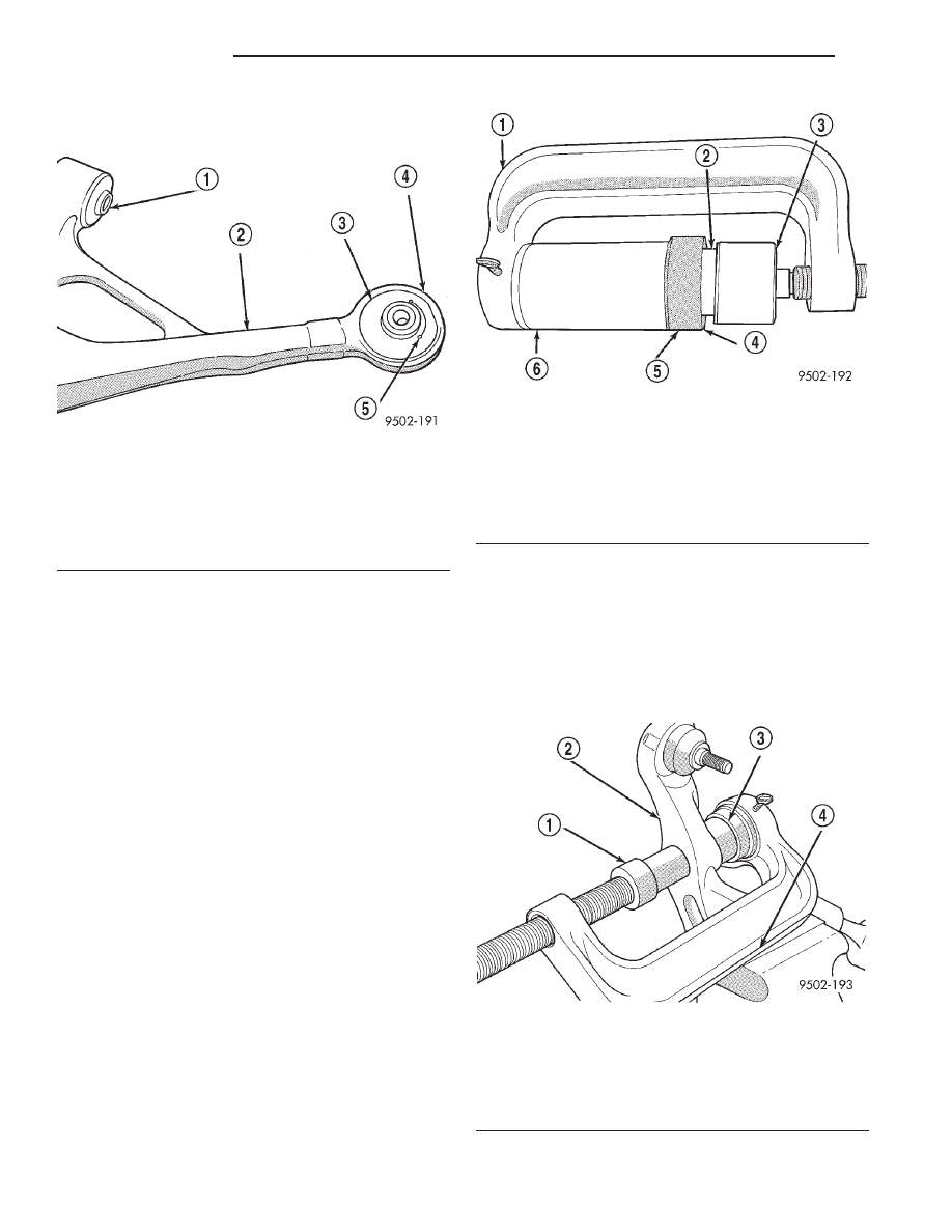
portion of bushing facing away from ball joint (Fig.
84).
(2) Mount Bushing Installer, Special Tool 6760 on
screw
portion
of
Remover/Installer
Special
Tool
C-4212-F (Fig. 85).
(3) Install Special Tools assembled for installation
of rear isolator bushing into lower control arm on the
lower control arm. Be sure Special Tool 6756 is
square on lower control arm and Special Tool 6760 is
positioned correctly on isolator bushing (Fig. 85).
(4) Tighten screw on Remover/Installer Special
Tool C-4212-F pressing rear bushing into lower con-
trol arm. Continue pressing rear bushing into lower
control arm until bushing is sitting flush on the
machined surface (Fig. 85) of the lower control arm.
This will correctly position rear bushing in lower con-
trol arm.
(5) Install lower control arm assembly back on
vehicle. See Lower Control Arm Installation in this
section of the service manual for the required instal-
lation procedure.
CONTROL ARM CLEVIS BUSHING
To perform removal and replacement of the lower
control arm clevis bushing, the lower control arm
must be removed from the vehicle.
DISASSEMBLE
(1) Remove lower control arm assembly from vehi-
cle. See Lower Control Arm Removal in this section
of the service manual for the required removal proce-
dure.
(2) Install Bushing Remover, Special Tool 6877 and
Bushing Receiver, Special Tool 6876 on Special Tool
C-4212-F.
(3) Install lower control arm on Special Tools
assembled for removal of the clevis isolator bushing.
Be sure Special Tool 6876 is square on lower control
arm and Special Tool 6877 is positioned correctly on
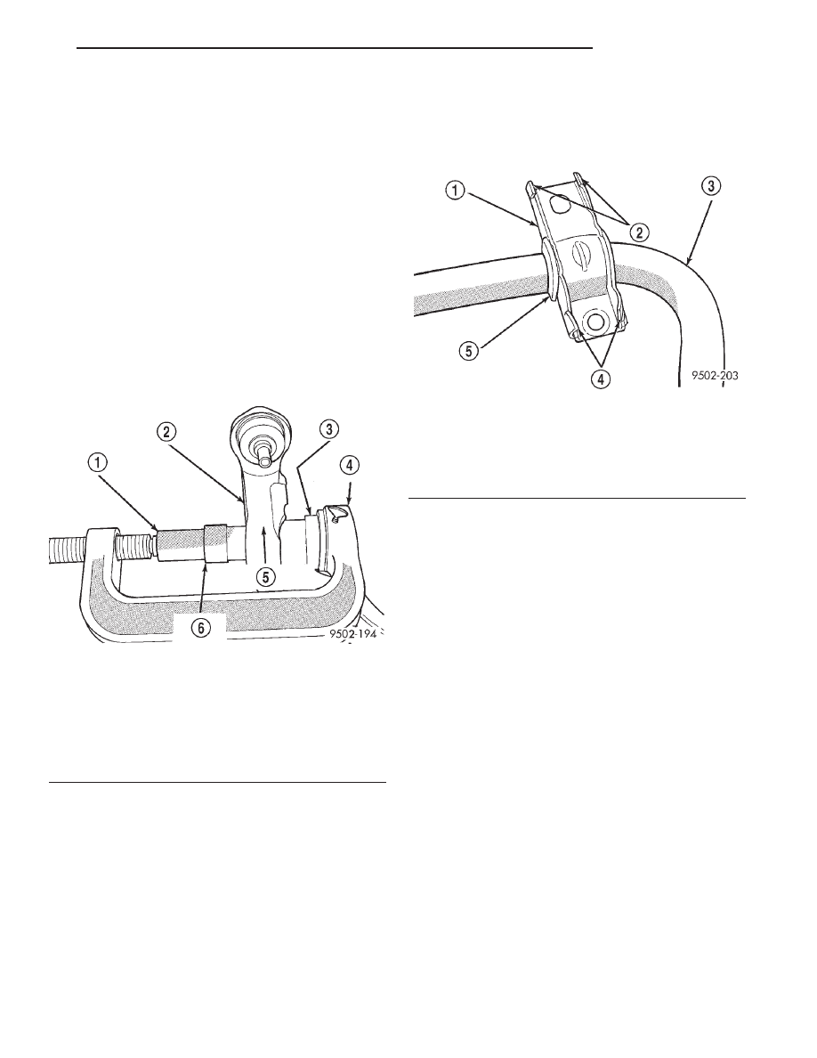
clevis bushing (Fig. 86).
Fig. 84 Correctly Positioned Rear Isolator Bushing
In Control Arm
1 – FRONT ISOLATOR BUSHING
2 – LOWER CONTROL ARM
3 – REAR ISOLATOR BUSHING
4 – MACHINED SURFACE
5 – VOID IN BUSHING IN THIS DIRECTION
Fig. 85 Installing Rear Bushing In Lower Control
Arm
1 – SPECIAL TOOL C-4212–F
2 – REAR BUSHING
3 – SPECIAL TOOL 6760
4 – MACHINED SURFACE ON LOWER CONTROL ARM
5 – LOWER CONTROL ARM
6 – SPECIAL TOOL 6756
Fig. 86 Removing Clevis Bushing From Lower
Control Arm
1 – SPECIAL TOOL 6877
2 – LOWER CONTROL ARM
3 – SPECIAL TOOL 6876
4 – SPECIAL TOOL C-4212–F
2 - 42
SUSPENSION
JX
DISASSEMBLY AND ASSEMBLY (Continued)
(4) Tighten screw on Remover/Installer Special
Tool C-4212-F to press clevis bushing out of lower
control arm.
ASSEMBLE
(1) Start clevis bushing into lower control arm by
hand, making sure it is square with its mount-
ing hole in the lower control arm. Bushing is to
be installed in lower control arm from the machined
surface side of lower control arm bushing hole.
(2) Mount Bushing Installer, Special Tool 6877 on
screw
portion
of
Remover/Installer
Special
Tool
C-4212-F as shown in (Fig. 87).
(3) Install the assembled special tools for installing
the clevis bushing into the lower control arm, on the
lower control arm and clevis bushing (Fig. 87). Be
sure Special Tool 6876 is square on lower control arm
and Special Tool 6877 is positioned correctly on clevis
bushing (Fig. 87).
(4) Tighten screw on Remover/Installer Special
Tool C-4212-F pressing clevis bushing into lower con-
trol arm. Continue pressing clevis bushing into lower
control arm until bushing is sitting flush with the
machined surface of the lower control arm. This will
correctly position the clevis bushing in the lower con-
trol arm.
(5) Install lower control arm assembly back on
vehicle. See Lower Control Arm Installation in this
section of the service manual for the required instal-
lation procedure.
STABILIZER BAR BUSHING (FRONT)
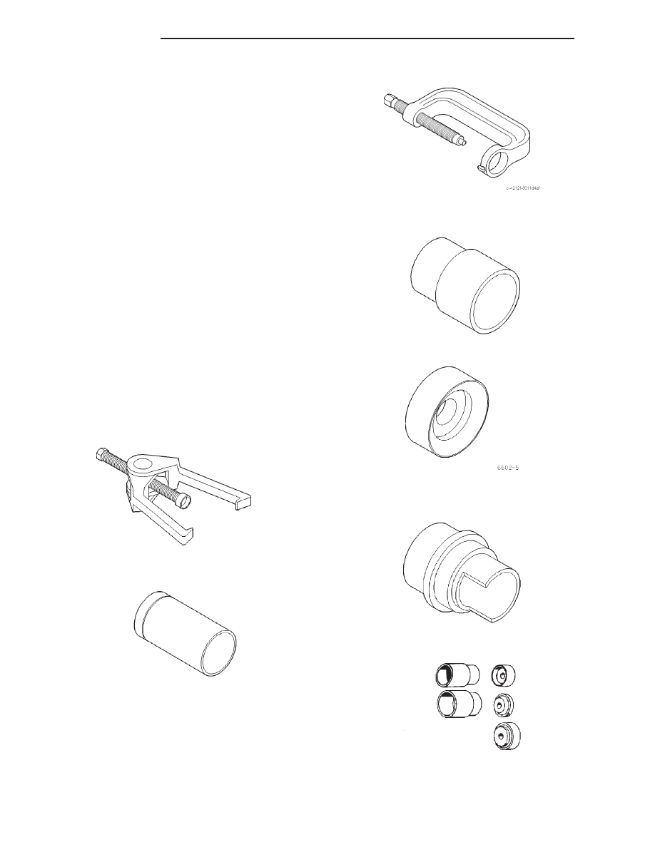
(1) Bend back the 4 crimp locations on the stabi-
lizer bar bushing retainer (Fig. 88).
(2) Separate the stabilizer bar bushing retainer.
(3) Stabilizer bar bushings are removed by opening
slit and peeling bushing off stabilizer bar.
(4) Install new stabilizer bar bushings on the sta-
bilizer bar. Bushings must be installed on sway
bar with slit in bushing facing front of vehicle
when sway bar is installed.
(5) Install bushing retainers back on stabilizer bar
bushings.
SPECIFICATIONS
FRONT SUSPENSION FASTENER TORQUE
SPECIFICATIONS
DESCRIPTION
TORQUE
Shock Assembly
Clevis Pinch Bolt . . . . . . . . . . 88 N·m (65 ft. lbs.)
Shock Tower Bolts . . . . . . . . 101 N·m (75 ft. lbs.)
Clevis To Control Arm Bolt . . 88 N·m (65 ft. lbs.)
Rod To Upper Mount Nut . . . 54 N·m (40 ft. lbs.)
Steering Knuckle
Disc Brake Caliper Bolts . . . . 22 N·m (16 ft. lbs.)
Tie Rod Nut . . . . . . . . . . . . . . 61 N·m (45 ft. lbs.)
Tie Rod Adjustment Jam Nuts . . . . . . . . . 61 N·m
(45 ft. lbs.)
Fig. 87 Installing Clevis Bushing In Lower Control
Arm
1 – SPECIAL TOOL 6877
2 – MACHINED SURFACE SIDE OF LOWER CONTROL ARM
3 – SPECIAL TOOL 6876
4 – SPECIAL TOOL C-4212–F
5 – LOWER CONTROL ARM
6 – CLEVIS BUSHING
Fig. 88 Stabilizer Bar Bushing Retainer
1 – STABILIZER BAR BUSHING RETAINER
2 – CRIMPS
3 – STABILIZER BAR
4 – CRIMPS
5 – STABILIZER BAR BUSHING
JX
SUSPENSION
2 - 43
DISASSEMBLY AND ASSEMBLY (Continued)
DESCRIPTION
TORQUE
Hub And Bearing
To Stub Axle Retaining Nut . . . . . . . . . . 244 N·m
(180 ft. lbs.)
Wheel Stud Lug Nut . . . . . . . . . . . . 109-150 N·m
(80-110 ft. lbs.)
Upper Control Arm
Ball Joint Stud Castle Nut . . 54 N·m (40 ft. lbs.)
Shock Bracket . . . . . . . . . . . . 90 N·m (66 ft. lbs.)
Lower Control Arm
Ball Joint Stud Castle Nut . . 74 N·m (55 ft. lbs.)
Crossmember Pivot Bolt (Front) . . . . . . 183 N·m
(135 ft. lbs.)
Crossmember Rear Bolt . . . . . 95 N·m (70 ft. lbs.)
Ball Joint Heat Shield Attaching Bolts . . 13 N·m
(10 ft. lbs.)
Stabilizer Bar
Bushing Clamp Bolts . . . . . . . 61 N·m (45 ft. lbs.)
Attaching Link Nuts (All) . . 101 N·m (75 ft. lbs.)
Front Suspension Crossmember
Body Mounting Bolts . . . . . . 108 N·m (80 ft. lbs.)
Steering Gear Mounting Bolts . . . . . . . . . 68 N·m
(50 ft. lbs.)
SPECIAL TOOLS
FRONT SUSPENSION
Puller C-3894-A
Installer, Ball Joint 6758
Press, Ball Joint Remover Installer C-4212F
Remover, Ball Joint MB-990799
Remover/Installer Control Arm Bushing 6602–5 (In
Tool Kit 6602)
Installer/Receiver, Control Arm Bushing 6876
Remover / Installer C-4366-2 (In Tool Kit C-4366)
2 - 44
SUSPENSION
JX
SPECIFICATIONS (Continued)
Нет комментариевНе стесняйтесь поделиться с нами вашим ценным мнением.
Текст