
Chrysler Stratus Convertible. Manual — part 59
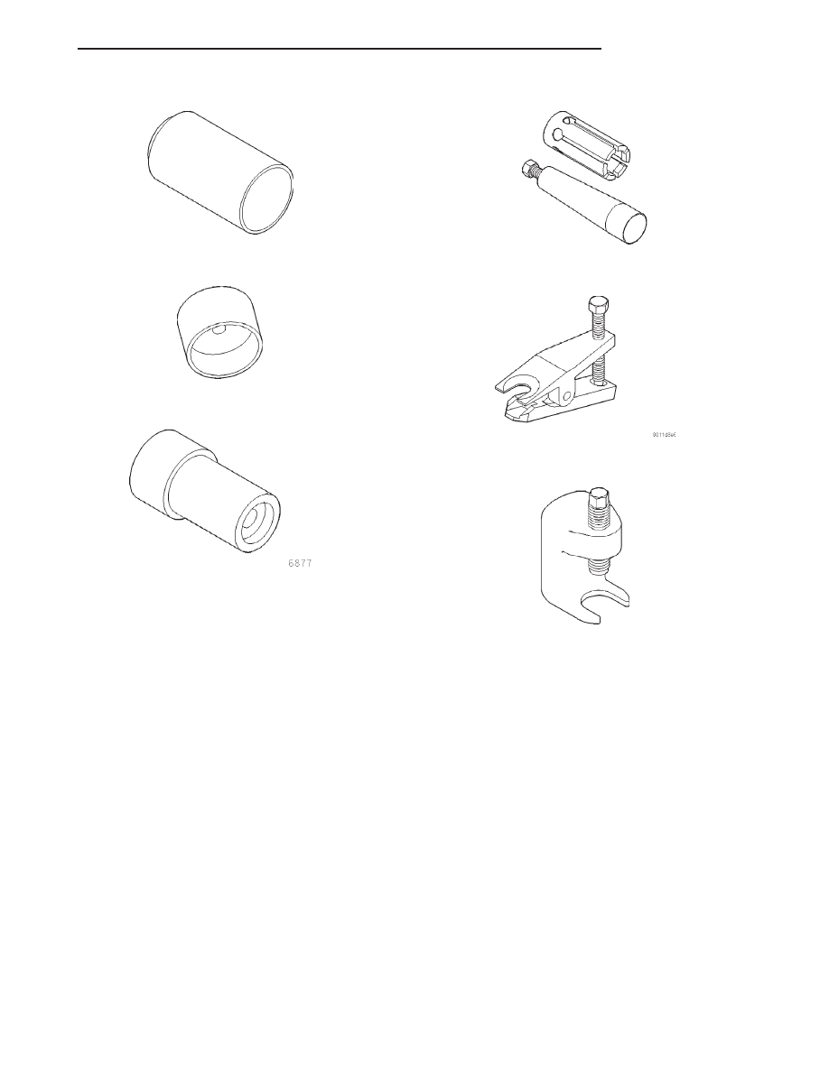
Receiver, Ball Joint 6756
Installer, Bushing 6760
Remover/Installer Control Arm Clevis Bushing 6877
Installer, Ball Joint Seal Boot Retainer 6875
Remover, Tie Rod End MB-991113 or MB-990635
Remover, Lower Ball Joint C-4150A
JX
SUSPENSION
2 - 45
SPECIAL TOOLS (Continued)
REAR SUSPENSION
TABLE OF CONTENTS
page
page
DESCRIPTION AND OPERATION
REAR SUSPENSION SYSTEM . . . . . . . . . . . . . . . 46
SHOCK ASSEMBLY (REAR) . . . . . . . . . . . . . . . . . 48
KNUCKLE (REAR) . . . . . . . . . . . . . . . . . . . . . . . . 48
HUB AND BEARING (REAR) . . . . . . . . . . . . . . . . 48
UPPER CONTROL ARM (REAR) . . . . . . . . . . . . . 49
LATERAL LINKS. . . . . . . . . . . . . . . . . . . . . . . . . . 49
TRAILING LINK . . . . . . . . . . . . . . . . . . . . . . . . . . 49
STABILIZER BAR (REAR). . . . . . . . . . . . . . . . . . . 49
DIAGNOSIS AND TESTING
SHOCK ASSEMBLY (REAR) . . . . . . . . . . . . . . . . . 49
KNUCKLE (REAR) . . . . . . . . . . . . . . . . . . . . . . . . 49
HUB AND BEARING (REAR) . . . . . . . . . . . . . . . . 49
UPPER CONTROL ARM (REAR) . . . . . . . . . . . . . 50
BALL JOINT (REAR UPPER) . . . . . . . . . . . . . . . . 50
LATERAL LINKS. . . . . . . . . . . . . . . . . . . . . . . . . . 50
TRAILING LINK . . . . . . . . . . . . . . . . . . . . . . . . . . 50
STABILIZER BAR (REAR). . . . . . . . . . . . . . . . . . . 50
SERVICE PROCEDURES
LUBRICATION . . . . . . . . . . . . . . . . . . . . . . . . . . . 50
REMOVAL AND INSTALLATION
SERVICE WARNINGS AND CAUTIONS . . . . . . . . 50
SHOCK ASSEMBLY (REAR) . . . . . . . . . . . . . . . . . 51
KNUCKLE (REAR) . . . . . . . . . . . . . . . . . . . . . . . . 53
HUB AND BEARING (REAR) . . . . . . . . . . . . . . . . 56
UPPER CONTROL ARM (REAR) . . . . . . . . . . . . . 57
LATERAL LINKS. . . . . . . . . . . . . . . . . . . . . . . . . . 60
TRAILING LINK . . . . . . . . . . . . . . . . . . . . . . . . . . 62
STABILIZER BAR (REAR). . . . . . . . . . . . . . . . . . . 63
DISASSEMBLY AND ASSEMBLY
SHOCK ASSEMBLY (REAR) . . . . . . . . . . . . . . . . . 64
BALL JOINT (REAR UPPER) . . . . . . . . . . . . . . . . 68
SPECIFICATIONS
REAR SUSPENSION FASTENER TORQUE
SPECIFICATIONS . . . . . . . . . . . . . . . . . . . . . . . 69
SPECIAL TOOLS
REAR SUSPENSION . . . . . . . . . . . . . . . . . . . . . . 70
DESCRIPTION AND OPERATION
REAR SUSPENSION SYSTEM
DESCRIPTION
The rear suspension used on this vehicle is a fully
independent short and long arm style suspension
(Fig. 1).
Each side of the rear suspension consists of these
major components:
• a shock assembly
• a knuckle
• an upper control arm
• two lateral links
• a trailing link
• a stabilizer bar
OPERATION
The rear suspension allows each rear wheel on
vehicle to adapt to different road surfaces and condi-
tions without affecting the control of the vehicle.
Each side of the suspension is allowed to move inde-
pendently from the other.
2 - 46
SUSPENSION
JX
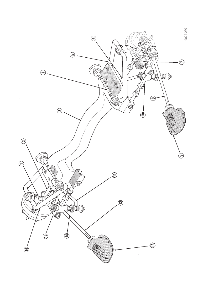
Fig.
1
Fully
Independent
Rear
Suspension
JX
SUSPENSION
2 - 47
DESCRIPTION AND OPERATION (Continued)
SHOCK ASSEMBLY (REAR)
DESCRIPTION
The rear shock absorber assemblies support the
weight of the vehicle using coil springs positioned
around the shock absorbers. The coil springs are con-
tained between the upper mount of the shock
absorber and a lower spring seat on the body of the
shock absorber.
The top of each shock absorber assembly is bolted
to the top of the inner fender through a rubber iso-
lated mount.
The
bottom
of
the
shock
absorber
assembly
attaches to the rear knuckle using a through-bolt.
The rear coil springs are rated separately for each
corner or side of the vehicle depending on optional
equipment and type of vehicle service. Coil springs
come in a various rates; be sure the correct spring is
in use.
The components of the shock assembly listed below
are serviceable:
• Shock rod nut
• Shock mount
• Shock rod bushings
• Upper spring isolator
• Dust shield
• Cup
• Jounce bumper
• Lower spring isolator
• Coil spring
• Strut
OPERATION
The shock absorber assembly cushions the ride of
the vehicle, controlling vibration, jounce and rebound
of the suspension.
The coil spring controls ride quality and maintains
ride height.
The jounce bumper limits suspension travel and
metal-to-metal contact under full jounce.
The shock absorber dampens jounce and rebound
motions of the coil spring and suspension.
KNUCKLE (REAR)
DESCRIPTION
A cast iron rear knuckle is attached to each side of
the vehicle through the upper control arm and ball
joint, the rear shock assembly, the lateral links and
the trailing link. The knuckle serves as a mounting
point for the rear hub and bearing, tire and wheel,
and rear brakes.
OPERATION
The knuckle moves up and down with the tire and
wheel under jounce and rebound conditions while
acting as a mount for the rear hub and bearing, tire
and wheel, and rear brakes. The lateral movement of
the rear knuckle is controlled using two lateral arms
attached to the bottom of the knuckle and by the
upper control arm attached to the top of the knuckle.
HUB AND BEARING (REAR)
DESCRIPTION
The hub and bearing is a combined rear wheel hub
and wheel bearing unit. All vehicles are equipped
with permanently lubricated and sealed for life rear
hub and bearing assemblies. There is no periodic
lubrication or maintenance recommended for these
units.
The hub and bearing is mounted to the rear knuck-
le’s spindle using a retaining nut. The tire and wheel
assembly, and rear brake drum or disc attaches to
the studs protruding from the hub flange with wheel
mounting studs.
1 – KNUCKLE
2 – REAR LATERAL LINK
3 – REAR SUSPENSION CROSSMEMBER
4 – UPPER CONTROL ARM PIVOT BAR
5 – UPPER CONTROL ARM
6 – REAR LATERAL LINK
7 – REAR KNUCKLE
8 – TRAILING LINK
9 – TRAILING LINK BRACKET
10 – FORWARD LATERAL LINK
11 – STABILIZER BAR
12 – TRAILING LINK
13 – TRAILING LINK BRACKET
14 – STABILIZER BAR ATTACHING LINK
15 – FORWARD LATERAL ARM
16 – UPPER CONTROL ARM
2 - 48
SUSPENSION
JX
DESCRIPTION AND OPERATION (Continued)
Нет комментариевНе стесняйтесь поделиться с нами вашим ценным мнением.
Текст