
Chrysler Stratus Convertible. Manual — part 228
BATTERY OPEN CIRCUIT VOLTAGE TEST
An open circuit voltage no load test shows the
state of charge of a battery and whether it is ready
for a load test at 50 percent of the battery’s cold
crank rating. Refer to Battery Load Test. If a battery
has open circuit voltage reading of 12.4 volts or
greater, and will not pass the load test, replace the
battery because it is defective. To test open circuit
voltage, perform the following operation.
(1) Remove both battery cables, negative cable
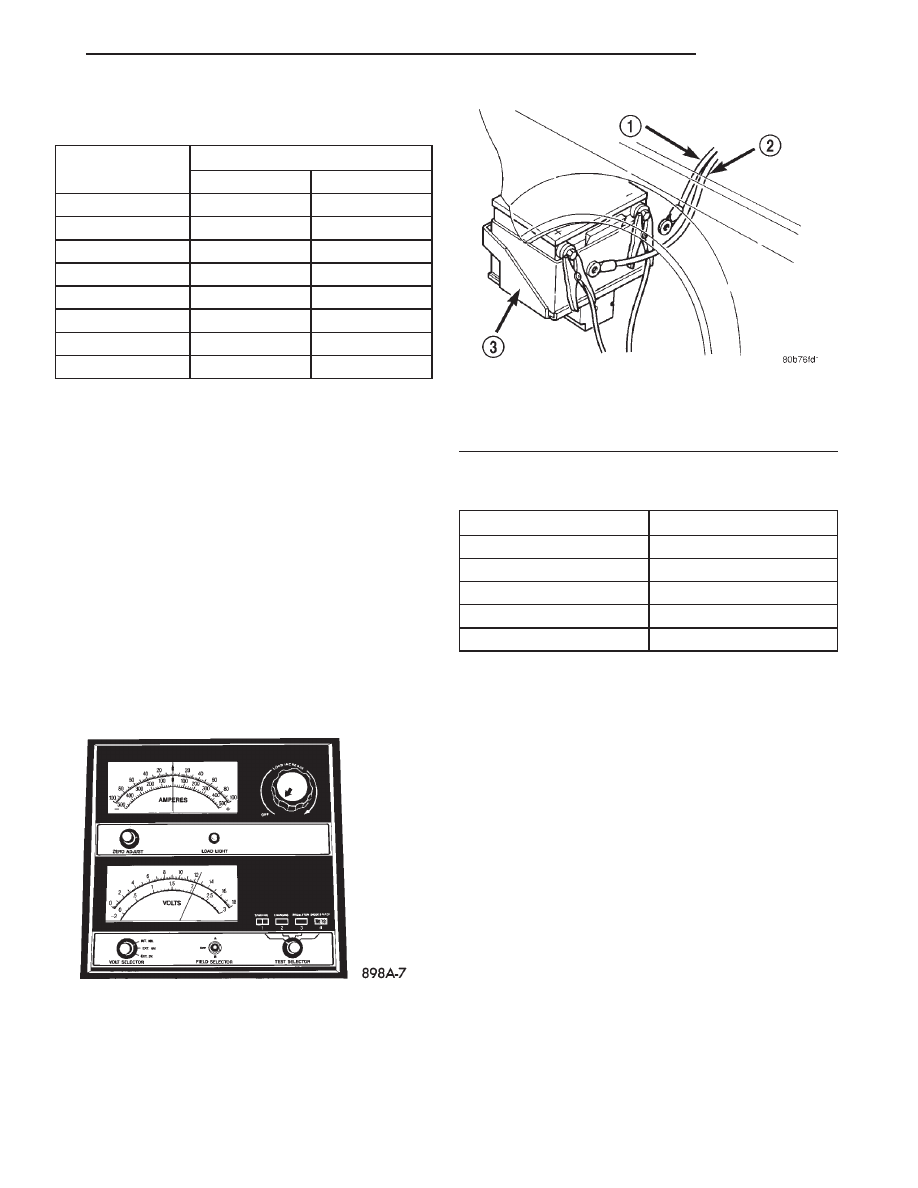
first. Connect a Volt/Ammeter/Load tester (Fig. 8) to
the battery posts (Fig. 9).
(2) Allow the battery to stabilize for 2 minutes,
and then verify the open circuit voltage. Refer to Bat-
tery Open Circuit Voltage table.
(3) This voltage reading will approximate the state
of charge of the battery. It will not reveal battery
cranking capacity.
IGNITION OFF DRAW TESTS (IOD)
High battery current draw when the ignition
switch in the off position will discharge a battery.
After a dead battery is serviced, the vehicle Ignition
Off Draw (IOD) should be checked. To determine if a
high current draw condition exists, check the vehicle
with a Digital multimeter that has an ammeter
range from at least 10 amps down to 10 milliamps
(30) milliamps is allowable.
(1) Verify all electrical accessories are OFF:
• Remove key from ignition switch
• Turn off all lamps
• Trunk compartment lamp is disconnected or
removed
• Glove box lamp goes off when the door is closed
• All doors are closed
• Sun visor vanity lamps are OFF
(2) Disconnect battery negative remote cable.
CAUTION: Do not operate any accessory that has a
greater draw than the ammeter can measure.
BATTERY LOAD TEMPERATURE TABLE
Minimum Voltage
Temperature
°F
°C
9.6 volts
70° and above
21° and above
9.5 volts
60°
16°
9.4 volts
50°
10°
9.3 volts
40°
4°
9.1 volts
30°
-1°
8.9 volts
20°
-7°
8.7 volts
10°
-12°
8.5 volts
0°
-18°
Fig. 8 Testing Open Circuit Voltage
Fig. 9 Volt-Ammeter Load Tester Connections
1 – BATTERY NEGATIVE CABLE
2 – BATTERY POSITIVE CABLE
3 – BATTERY
BATTERY OPEN CIRCUIT VOLTAGE
Open Circuit Volts
Charge Percentage
11.7 volts or less
0%
12.0 volts
25%
12.2 volts
50%
12.4 volts
75%
12.6 volts or more
100%
JX
BATTERY
8A - 5
DIAGNOSIS AND TESTING (Continued)

(3) Using a Digital multi-meter, set to 10 amps
and connect leads between the battery negative
remote terminal and the battery negative remote
cable stud.
(a) Remove the “Seat Belt” (20 amp max) AND
the “EATX” (20 amp min) fuses from the PDC.
(b) Wait (1) minute.
(c) If the reading is greater than 30 milliamps,
go to HIGH MILLIAMP READING.
(d) Reinstall the EATX fuse.
(e) If the draw increases, remove the fuse again
and immediately reinstall the fuse. If the draw
increases again, repeat the remove and install pro-
cess (2) or (3) times. If the draw continues to
increase, it will be necessary to wait for up to (20)
minutes to see if the draw drops. If it does not, the
problem will be in the EATX module or circuit.
(f) If the draw remains under (30) milliamps,
there is not a problem with an “Ignition Off Draw”.
If the draw did increase, it will be necessary to
wait for (30) minutes. If it does not, the problem
might be with the SCTM or seat belt circuit. Verify
SCTM time-out.
(g) To enable the SCTM to time-out in (30) sec-
onds, perform the following:
• (4) key cycles within (4) seconds.
• Pull radio fuse if RAZ radio equipped (Integrat-
ed CD and Cassette). The diagnostic mode will reflect
an unlocked seat belt if the doors are open (door ajar
switch closed), and a locked seat belt condition if the
doors are closed (door ajar switch open).
NOTE: Each time the ammeter is disconnected and
reconnected, all electronic timer functions will be
reactivated.
HIGH MILLIAMPERE READING
NOTE: Perform BATTERY IGNITION OFF DRAW
TEST before proceeding.
If the IOD is high, there is either a short circuit or
a fault in an electronic module. There are (6) other
fuses in the Power Distribution Center and Junction
Block that feed the modules with ignition off draw.
Ensure that all electronic timer functions are timed
out before testing any of the components.
IN THE POWER DISTRIBUTION CENTER
• Ignition Fuel Starter (20 Amp)
• Hazard Flasher (20 Amp)
• EATX (20 Amp min) (previously tested)
• Seat Belt (20 Amp max) (previously tested)
• Stop Lamp (20 Amp)
IN THE JUNCTION BLOCK:
• Daytime Running Lamps (DRL) (20 Amp)
• Horns-Cigar Lighter (20 Amp)
• Interior lamps (10 Amp) (IOD)
• Park/tail lamps-Instrument Cluster (20 Amp)
NOTE: Do not operate any accessory that has a
greater draw than the installed ammeter can mea-
sure.
Replace fuses one at a time. The module should
draw a few milliamps when the fuse is replaced. If it
draws in excess of (20) milliamps (not including
timed out functions) then the module should be
replaced or wiring should be investigated. Refer to
Group 8W-Wiring Diagrams. Check for faulty sys-
tems operations or module fault codes to help find
wiring faults. Be sure you have double checked other
possible IOD draws. Refer to IOD Draw Table.
To determine if a module draw is within acceptable
range, refer to the Module Amperage Table for IOD
readings.
IOD DRAW TABLE
COMPONENT
AMPERAGE DRAW
STUCK RELAY
0.25 AMP
ILLUMINATED BULB
0.25 - 1 AMP
RADIO MEMORY
1 - 4 ma
BCM
8 ma (TIMED OUT)
TRUNK SOLENOID
STUCK ON
0.5 AMP
8A - 6
BATTERY
JX
DIAGNOSIS AND TESTING (Continued)
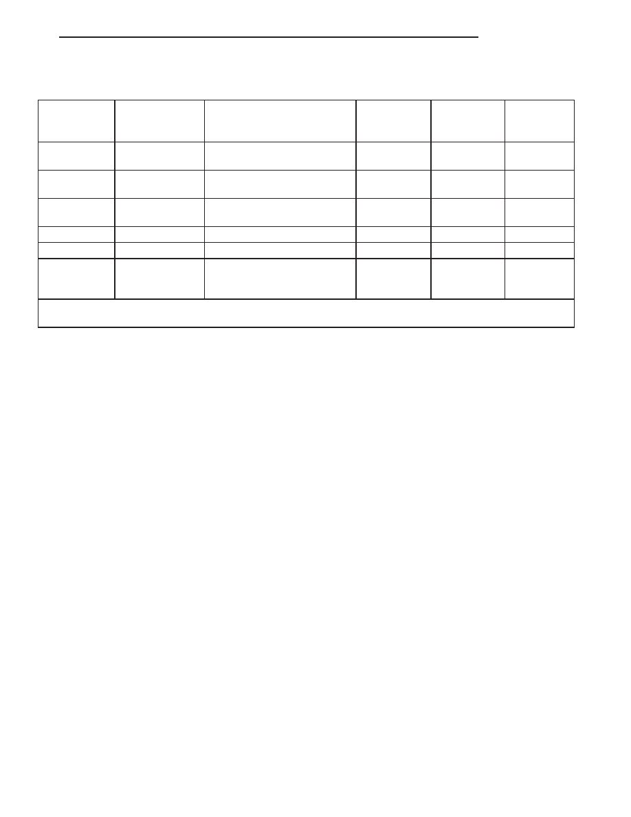
MODULE AMPERAGE TABLE
FUSE NO.
MODULE
INITIALIZER
TIMEOUT
DRAW
DURING
TIMEOUT
DRAW
AFTER
TIMEOUT
#4
BCM - LAMPS
RKE, DOOR AJAR,
IGNITION KEY ON
0.5 MIN.
3.0 AMPS
0
#5 & #10
PCM
IGNITION KEY ON
0.5 MIN.
UP TO 4
AMPS
1.3 ma
#4
BCM - MICRO-
PROCESSOR
DOOR AJAR, IGNITION KEY
ON
1 MIN.
60 ma
7 ma
#6
SKIM
IGNITION KEY ON
5 MIN.
60 ma
7 ma
#3
EATX
IGNITION KEY ON
20 MIN.
60 ma
0.8 ma
#13
SCTM
DOOR AJAR, IGNITION KEY
TURNED FROM RUN OR
ACCESSORY TO OFF
30 MIN.
400 ma
1.5 ma
NOTE: MAKE SURE DOOR IS CLOSED WHEN CHECKING BCM AND LAMPS. DOOR AJAR SWITCHES WILL
KEEP BCM FROM TIMING OUT.
NOTE: To check to see if SCTM is initialized, pull
on the seat belt and if it is locked the module is not
initialized or “Awake”.
SERVICE PROCEDURES
SAFETY PRECAUTIONS AND WARNINGS
WARNING: WEAR SAFETY GLASSES.
DO NOT ALLOW JUMPER CABLE CLAMPS TO
TOUCH EACH OTHER WHEN CONNECTED TO A
BOOSTER SOURCE.
DO NOT USE OPEN FLAME NEAR BATTERY.
REMOVE METALLIC JEWELRY WORN ON HANDS
OR WRISTS TO AVOID INJURY BY ACCIDENTAL
ARCING OF BATTERY CURRENT.
WHEN
USING
A
HIGH
OUTPUT
BOOSTING
DEVICE, DO NOT ALLOW THE DISABLED VEHI-
CLE’S BATTERY TO EXCEED 16 VOLTS. PER-
SONAL INJURY OR DAMAGE TO ELECTRICAL
SYSTEM CAN RESULT.
TO PROTECT THE HANDS FROM BATTERY ACID,
A SUITABLE
PAIR
OF
HEAVY DUTY RUBBER
GLOVES, NOT THE HOUSEHOLD TYPE, SHOULD
BE WORN WHEN REMOVING OR SERVICING A
BATTERY. SAFETY GLASSES ALSO SHOULD BE
WORN.
BATTERY CHARGING
A battery is considered fully charged when it will
meet all the following requirements.
• It has an open circuit voltage charge of at least
12.4 volts (refer to Battery Open Circuit Voltage
table).
• It passes the 15 second load test, refer to Bat-
tery Load Test Temperatures Table.
WARNING: DO NOT ASSIST BOOST OR CHARGE A
FROZEN BATTERY.
EXPLOSIVE GASES FORM OVER THE BATTERY,
DO
NOT
SMOKE,
USE
FLAME,
OR
CREATE
SPARKS NEAR BATTERY.
CAUTION: Disconnect the battery NEGATIVE cable
first, before charging battery to avoid damage to
electrical systems. Do not exceed 16.0 volts while
charging battery. Refer to the instructions supplied
with charging equipment.
Battery electrolyte will bubble inside of battery
case while being charged properly. If the electrolyte
boils violently, or is discharged from the vent holes
while charging, immediately reduce charging rate or
turn off charger. Evaluate battery condition. Battery
damage may occur if charging is excessive.
Some battery chargers are equipped with polarity
sensing devices to protect the charger or battery from
being damaged if improperly connected. If the bat-
tery state of charge is too low for the polarity sensor
to detect, the sensor must be bypassed for charger to
operate. Refer to operating instructions provided
with battery charger being used.
CAUTION: Do not overcharge Battery. Refer to Bat-
tery Charging Rate table.
JX
BATTERY
8A - 7
DIAGNOSIS AND TESTING (Continued)
After the battery has been charged to 12.4 volts or
greater, perform a load test to determine cranking
capacity. Refer to Battery Load Test in this Group. If
the battery will endure a load test, return the bat-
tery to use. If battery will not endure a load test, it
must be replaced. Properly clean and inspect battery
hold downs, tray, terminals, cables, posts, and top
before completing service.
BATTERY CHARGING TIME REQUIRED
WARNING: NEVER
EXCEED
20
AMPS
WHEN
CHARGING A COLD -1°C (30°F) BATTERY. PER-
SONAL INJURY MAY RESULT.
The time required to charge a battery will vary
depending upon the following factors.
SIZE OF BATTERY
A completely discharged large heavy-duty battery
may require more recharging time than a completely
discharged small capacity battery, refer to Battery
Charging Timetable for charging times.
TEMPERATURE
A longer time will be needed to charge a battery at
-18°C (0°F) than at 27°C (80°F). When a fast charger
is connected to a cold battery, current accepted by
battery will be very low at first. In time, the battery
will accept a higher rate as battery temperature
warms.
CHARGER CAPACITY
A charger which can supply only five amperes will
require a much longer period of charging than a
charger that can supply 20 amperes or more.
STATE OF CHARGE
A completely discharged battery requires more
charging time than a partially charged battery. Elec-
trolyte is nearly pure water in a completely dis-
charged
battery. At
first,
the
charging
current
amperage will be low. As water is converted back to
sulfuric acid inside the battery, the current amp rate
will rise. Also, the specific gravity of the electrolyte
will rise. Refer to Battery Charging procedures.
CHARGING COMPLETELY DISCHARGED
BATTERY
The following procedure should be used to recharge
a completely discharged battery. Unless procedure is
properly followed, a good battery may be needlessly
replaced. Refer to Battery Charging Rate table for
correct charge times.
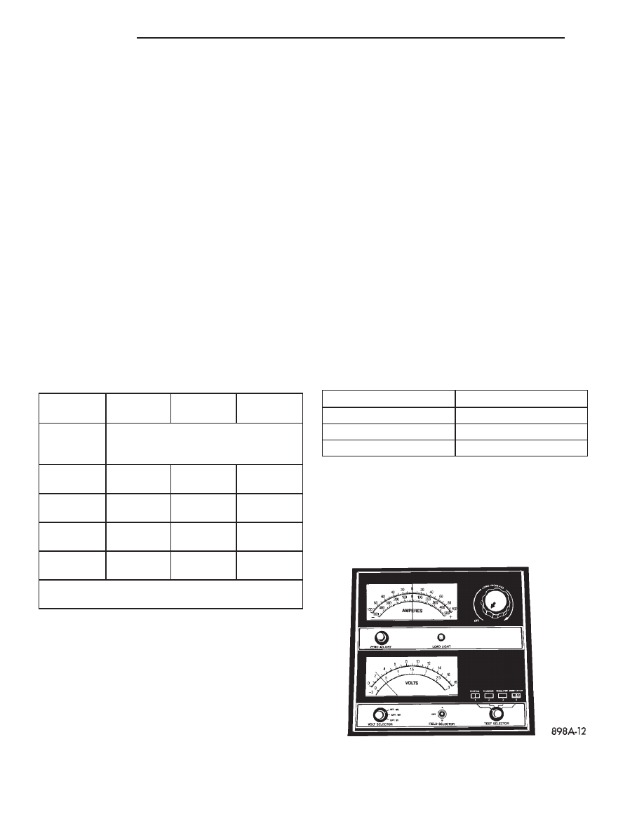
(1) Measure the voltage at remote cable terminals
with a voltmeter accurate to 1/10 volt (Fig. 10). If
below 10 volts, charge current will be low, and it
could take some time before it accepts a current in
excess of a few milliamperes. Such low current may
not be detectable on amp meters built into many
chargers.
BATTERY CHARGING TIMETABLE
CHARGING
AMPERAGE
5
AMPERES
10
AMPERES
20
AMPERES
OPEN
CIRCUIT
VOLTAGE
HOURS CHARGING AT 21° C (70° F)
12.25 TO
12.49
6 HOURS
3 HOURS
1.5
HOURS
12.00 TO
12.24
10
HOURS
5 HOURS
2.5
HOURS
10.00 TO
11.99
14
HOURS
7 HOURS
3.5
HOURS
*BELOW
10.00
18
HOURS
9 HOURS
4.5
HOURS
*REFER TO CHARGING A COMPLETELY
DISCHARGED BATTERY
BATTERY CHARGING RATE
Voltage
Hours
16.0 volts maximum
up to 4 hours
14.0 to 15.9 volts
up to 8 hours
13.9 volts or less
up to 16 hours
Fig. 10 Voltmeter Accurate to 1/10 Volt (Connected)
8A - 8
BATTERY
JX
SERVICE PROCEDURES (Continued)
Нет комментариевНе стесняйтесь поделиться с нами вашим ценным мнением.
Текст