
Chrysler Stratus Convertible. Manual — part 28
of voltage output from the sensor is usually between
4.6 volts at sea level to as low as 0.3 volts at 26 in. of
Hg (Table 1). Barometric pressure is the pressure
exerted by the atmosphere upon an object. At sea
level on a standard day, no storm, barometric pres-
sure is 29.92 in Hg. For every 100 feet of altitude
barometric pressure drops.10 in. Hg. If a storm goes
through it can either add, high pressure, or decrease,
low pressure, from what should be present for that
altitude. You should make a habit of knowing what
the average pressure and corresponding barometric
pressure is for your area. Always use the Diagnostic
Test Procedures Manual for MAP sensor testing.
POWER STEERING PRESSURE SWITCH—PCM
INPUT
DESCRIPTION
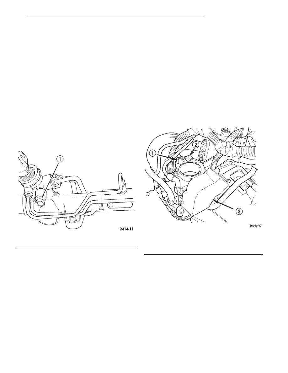
A pressure sensing switch is located on the power
steering gear.
OPERATION
The switch (Fig. 5) provides an input to the PCM
during periods of high pump load and low engine
RPM; such as during parking maneuvers.
When power steering pump pressure exceeds 4137
kPa (600 psi), the switch is open. The PCM increases
idle air flow through the IAC motor to prevent
engine stalling. When pump pressure is low, the
switch is closed.
SENSOR RETURN—PCM INPUT
OPERATION
The sensor return circuit provides a low electrical
noise ground reference for all of the systems sensors.
The sensor return circuit connects to internal ground
circuits
within
the
Powertrain
Control
Module
(PCM).
SCI RECEIVE—PCM INPUT
OPERATION
SCI Receive is the serial data communication
receive circuit for the DRB scan tool. The Powertrain
Control Module (PCM) receives data from the DRB
through the SCI Receive circuit.
THROTTLE POSITION SENSOR—PCM INPUT
DESCRIPTION
The throttle position sensor mounts to the side of
the throttle body (Fig. 6).
OPERATION
The Throttle Position Sensor (TPS) connects to the
throttle blade shaft. The TPS is a variable resistor
that provides the PCM with an input signal (voltage).
The signal represents throttle blade position. As the
position of the throttle blade changes, the resistance
of the TPS changes.
The PCM supplies approximately 5 volts DC to the
TPS. The TPS output voltage (input signal to the
PCM) represents throttle blade position. The TPS
output voltage to the PCM varies from approximately
0.5 volt at minimum throttle opening (idle) to a max-
imum of 3.7 volts at wide open throttle.
Along with inputs from other sensors, the PCM
uses TPS input to determine current engine operat-
ing conditions. The PCM also adjusts fuel injector
Fig. 5 Power Steering Pressure Switch
1 – POWER STEERING PRESSURE SWITCH
Fig. 6 Throttle Position Sensor—2.0L Engines
1 – TPS
2 – IAC
3 – THROTTLE CONTROL SHIELD
JX
FUEL SYSTEM
14 - 29
DESCRIPTION AND OPERATION (Continued)
pulse width and ignition timing based on these
inputs.
VEHICLE SPEED SIGNAL—PCM INPUT
DESCRIPTION
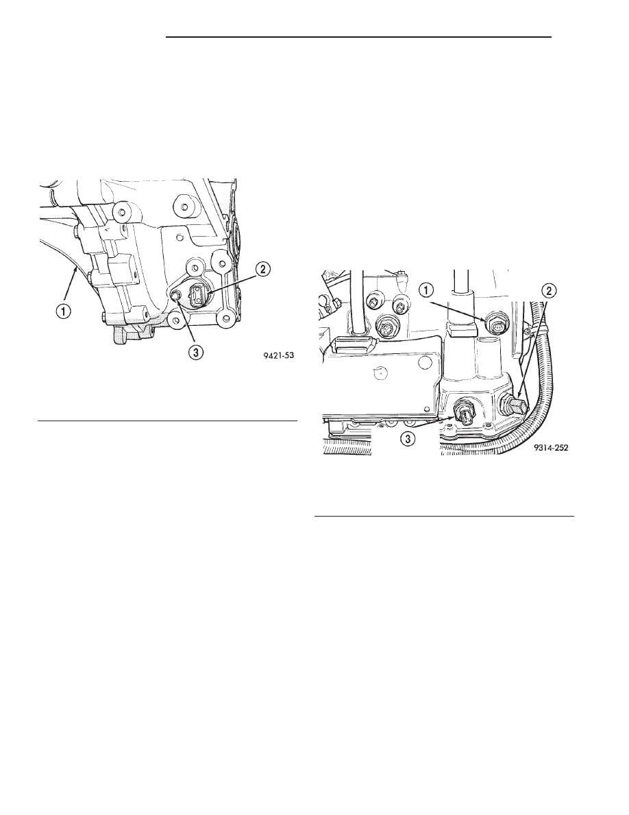
The vehicle speed sensor is located in the transmis-
sion extension housing (Fig. 7).
OPERATION
AUTOMATIC
The transaxle control module (TCM) supplies the
vehicle speed signal to the PCM based on the output
shaft speed. The PCM sends a 5 volt signal to the
TCM. The TCM switches this signal to a ground, and
then opens the circuit at a rate of 8000 pulses per
mile. When the PCM counts 8000 pulses, the PCM
assumes the vehicle has traveled one mile. The out-
put speed sensor is located on the side of the tran-
saxle (Fig. 8).
The speed and distance signals, along with a closed
throttle signal from the TPS, determine if a closed
throttle deceleration or normal idle condition (vehicle
stopped) exists. Under deceleration conditions, the
PCM adjusts the idle air control motor to maintain a
desired MAP value. Under idle conditions, the PCM
adjusts the idle air control motor to maintain a
desired engine speed.
MANUAL
The sensor input is used by the PCM to determine
vehicle speed and distance traveled.
The vehicle speed sensor generates 8 pulses per
sensor revolution. These signals, in conjunction with
a closed throttle signal from the throttle position sen-
sor, indicate a closed throttle deceleration to the
PCM.
Under
deceleration
conditions,
the
PCM
adjusts the Idle Air Control (IAC) motor to maintain
a desired MAP value.
When the vehicle is stopped at idle, a closed throt-
tle signal is received by the PCM (but a speed sensor
signal is not received). Under idle conditions, the
PCM adjusts the IAC motor to maintain a desired
engine speed.
The vehicle speed sensor signal is also used to
operate the following functions or systems:
• Speedometer
• Speed control
• Daytime Running Lights (Canadian Vehicles
only).
AUTOMATIC SHUTDOWN RELAY—PCM
OUTPUT
DESCRIPTION
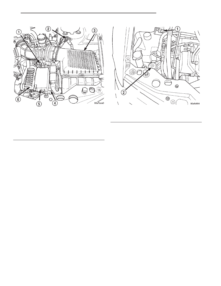
The ASD relay and fuel pump relay are located in
the Power Distribution Center (PDC) near the Air
Cleaner (Fig. 9). The inside top of the PDC cover has
a label showing relay and fuse location. They are ISO
relays.
OPERATION
The PCM operates the Automatic Shut Down
(ASD) relay and fuel pump relay through one ground
path. The PCM operates them by switching the
ground path for the relays on and off.
The ASD relay connects battery voltage to the fuel
injectors and ignition coil. The fuel pump relay con-
nects battery voltage to the fuel pump.
Fig. 7 Vehicle Speed Sensor—Manual Transmission
1 – TRANSAXLE
2 – SPEED SENSOR
3 – SPEED SENSOR RETAINING BOLT
Fig. 8 Output Speed Sensor—Automatic Transaxle
1 – OUTPUT SPEED SENSOR
2 – PARK/NEUTRAL SWITCH (BLACK)
3 – TRANSMISSION RANGE SWITCH
14 - 30
FUEL SYSTEM
JX
DESCRIPTION AND OPERATION (Continued)
The PCM turns the ground path off when the igni-
tion switch is in the Off position. Both relays are off.
When the ignition switch is in the On or Crank posi-
tion, the PCM monitors the crankshaft position sen-
sor
and
camshaft
position
sensor
signals
to
determine engine speed. If the PCM does not receive
a crankshaft position sensor signal and camshaft
position sensor signal when the ignition switch is in
the Run position, it de-energizes both relays. When
the relays are de-energized, battery voltage is not
supplied to the fuel injectors, ignition coil and fuel
pump.
PROPORTIONAL PURGE SOLENOID—PCM
OUTPUT
DESCRIPTION
The solenoid attaches to a bracket near the front
engine mount (Fig. 10). To operate correctly, the sole-
noid must be installed with the electrical connector
on top.
OPERATION
The purge solenoid regulates the rate of vapor flow
from the EVAP canister to the throttle body. The
PCM operates the solenoid.
During the cold start warm-up period and the hot
start time delay, the PCM does not energize the sole-
noid. When de-energized, no vapors are purged.
The proportional purge solenoid operates at a fre-
quency of 200 hz and is controlled by an engine con-
troller circuit that senses the current being applied
to the proportional purge solenoid and then adjusts
that current to achieve the desired purge flow. The
proportional purge solenoid controls the purge rate of
fuel vapors from the vapor canister and fuel tank to
the engine intake manifold.
IDLE AIR CONTROL MOTOR—PCM OUTPUT
DESCRIPTION
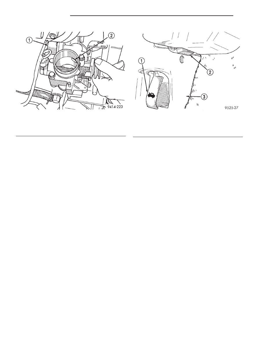
The Idle Air Control (IAC) motor is mounted on the
throttle body. The PCM operates the idle air control
motor (Fig. 11).
OPERATION
The PCM adjusts engine idle speed through the
idle air control motor to compensate for engine load,
coolant temperature or barometric pressure changes.
The throttle body has an air bypass passage that
provides air for the engine during closed throttle idle.
The idle air control motor pintle protrudes into the
air bypass passage and regulates air flow through it.
The PCM adjusts engine idle speed by moving the
IAC motor pintle in and out of the bypass passage.
The adjustments are based on inputs the PCM
receives. The inputs are from the throttle position
sensor, crankshaft position sensor, coolant tempera-
ture sensor, MAP sensor, vehicle speed sensor and
Fig. 9 Power Distribution Center (PDC)
1 – BATTERY POSITIVE
2 – BATTERY GROUND
3 – AIR CLEANER
4 – PCM
5 – PDC
6 – TCM
Fig. 10 Proportional Purge Solenoid
1 – TEST PORT
2 – PROPORTIONAL PURGE SOLENOID
JX
FUEL SYSTEM
14 - 31
DESCRIPTION AND OPERATION (Continued)
various switch operations (brake, park/neutral, air
conditioning).
When engine rpm is above idle speed, the IAC is
used for the following functions:
• Off-idle dashpot
• Deceleration air flow control
• A/C compressor load control (also opens the pas-
sage slightly before the compressor is engaged so
that the engine rpm does not dip down when the
compressor engages)
Target Idle
Target idle is determined by the following inputs:
• Gear position
• ECT Sensor
• Battery voltage
• Ambient/Battery Temperature Sensor
• VSS
• TPS
• MAP Sensor
DATA LINK CONNECTOR
DESCRIPTION
The data link connector is located inside the vehi-
cle, under the instrument panel, at the driver’s kick
panel (Fig. 12).
OPERATION
The data link connector (diagnostic connector)
links the DRB scan tool with the Powertrain Control
Module (PCM). Refer to On-Board Diagnostics in the
Emission Control section.
MALFUNCTION INDICATOR (CHECK ENGINE)
LAMP—PCM OUTPUT
DESCRIPTION
Refer to the Instrument Panel Systems for more
information.
OPERATION
The PCM supplies the malfunction indicator (check
engine) lamp on/off signal to the instrument panel
through the CCD Bus. The CCD Bus is a communi-
cations port. Various modules use the CCD Bus to
exchange information.
The Check Engine lamp comes on each time the
ignition key is turned ON and stays on for 3 seconds
as a bulb test.
The Malfunction Indicator Lamp (MIL) stays on
continuously, when the PCM has entered a Limp-In
mode or identified a failed emission component. Dur-
ing Limp-in Mode, the PCM attempts to keep the
system operational. The MIL signals the need for
immediate service. In limp-in mode, the PCM com-
pensates for the failure of certain components that
send incorrect signals. The PCM substitutes for the
incorrect signals with inputs from other sensors.
If the PCM detects active engine misfire severe
enough to cause catalyst damage, it flashes the MIL.
At the same time the PCM also sets a Diagnostic
Trouble Code (DTC).
For signals that can trigger the MIL (Check
Engine Lamp) refer to the On-Board Diagnos-
tics Chart.
Fig. 11 Idle Air Control Motor Air Bypass Passage—
2.0L
1 – IDLE AIR CONTROL MOTOR
2 – FRESH AIR OPENING
Fig. 12 Data Link (Diagnostic) Connector
1 – HOOD RELEASE
2 – DIAGNOSTIC CONNECTOR
3 – DRIVER’S SIDE KICK PANEL
14 - 32
FUEL SYSTEM
JX
DESCRIPTION AND OPERATION (Continued)
Нет комментариевНе стесняйтесь поделиться с нами вашим ценным мнением.
Текст