
Chrysler Stratus Convertible. Manual — part 27
NOTE: PCM Inputs:
• Air Conditioning Controls
• Battery Voltage
• Battery Temperature Sensor
• Brake Switch
• Camshaft Position Sensor
• Crankshaft Position Sensor
• CCD Bus
• Engine Coolant Temperature Sensor
• Fuel Level Sensor
• Ignition Switch
• Intake Air Temperature Sensor
• Knock Sensor (2.0L only)
• Leak Detection Pump
• Manifold Absolute Pressure (MAP) Sensor
• Oxygen Sensors
• Power Steering Pressure Switch
• SCI Receive
• Speed Control Switches
• Throttle Position Sensor
• Transmission Park/Neutral Switch (automatic
transmission)
• Vehicle Speed Sensor
NOTE: PCM Outputs:
• Air Conditioning Clutch Relay
• Auto Shutdown (ASD) Relay
• Charging Indicator Lamp
• CCD Bus
• SCI Transmit
• Proportional Purge Solenoid
• EGR Solenoid
• Fuel Injectors
• Fuel Pump Relay
• Generator Field
• Idle Air Control Motor
• Ignition Coils
• Malfunction Indicator (Check Engine) Lamp
• Radiator Fan Relays
• Speed Control Solenoids
Based on inputs it receives, the PCM adjusts fuel
injector pulse width, idle speed, ignition spark
advance, ignition coil dwell and EVAP canister purge
operation. The PCM regulates the cooling fan, air
conditioning and speed control systems. The PCM
changes generator charge rate by adjusting the gen-
erator field. The PCM also performs diagnostics.
The PCM adjusts injector pulse width (air-fuel
ratio) based on the following inputs.
• Battery voltage
• Coolant temperature
• Exhaust gas content (oxygen sensor)
• Engine speed (crankshaft position sensor)
• Intake air temperature
• Manifold absolute pressure
• Throttle position
The PCM adjusts ignition timing based on the fol-
lowing inputs.
• Coolant temperature
• Engine speed (crankshaft position sensor)
• Knock sensor
• Manifold absolute pressure
• Throttle position
• Transmission
gear
selection
(park/neutral
switch)
• Intake air temperature
The PCM also adjusts engine idle speed through
the idle air control motor based on the following
inputs.
• Air conditioning sense
• Battery voltage
• Battery temperature
• Brake switch
• Coolant temperature
• Engine speed (crankshaft position sensor)
• Engine run time
• Manifold absolute pressure
• Power steering pressure switch
• Throttle position
• Transmission
gear
selection
(park/neutral
switch)
• Vehicle distance (speed)
The Auto Shutdown (ASD) and fuel pump relays
are located in the Power Distribution Center (PDC).
The camshaft position sensor and crankshaft posi-
tion sensor signals are sent to the PCM. If the PCM
does not receive the signal within approximately 1
second of engine cranking, it deactivates the ASD
relay and fuel pump relay. When these relays are
deactivated, power is shut off from the fuel injectors,
ignition coils, oxygen sensor heating elements and
fuel pump.
The
PCM
contains
a
voltage
converter
that
changes battery voltage to a regulated 9 volts direct
current to power the camshaft position sensor, crank-
shaft position sensor and vehicle speed sensor. The
PCM also provides a 5 volt direct current supply for
the manifold absolute pressure sensor, throttle posi-
tion sensor, and A/C pressure switch.
AUTOMATIC SHUTDOWN (ASD) SENSE—PCM
INPUT
DESCRIPTION
It is an input to the Powertrain Control Module
from the rely in the Power Distribution Center, refer
to the cover for relay location.
OPERATION
The ASD sense circuit informs the PCM when the
ASD relay energizes. A 12 volt signal at this input
JX
FUEL SYSTEM
14 - 25
DESCRIPTION AND OPERATION (Continued)
indicates to the PCM that the ASD has been acti-
vated. This input is used only to sense that the ASD
relay is energized.
When energized, the ASD relay provides power to
operate the injectors, ignition coil, generator field, O2
sensor heaters (both upstream and downstream), and
also provides a sense circuit to the PCM for diagnos-
tic purposes. The PCM energizes the ASD any time
there is a Crankshaft Position sensor signal that
exceeds a predetermined value. The ASD relay can
also be energized after the engine has been turned
off to perform an O2 sensor heater test, if vehicle is
equipped with OBD II diagnostics.
With SBEC III, the ASD relay’s electromagnet is
fed battery voltage, not ignition voltage. The PCM
still provides the ground. As mentioned earlier, the
PCM energizes the ASD relay during an O2 sensor
heater test. This test is performed only after the
engine has been shut off. The PCM still operates
internally to perform several checks, including moni-
toring the O2 sensor heaters. This and other DTC
tests are explained in detail in the On-Board Diag-
nostic Student Reference Book.
BATTERY VOLTAGE—PCM INPUT
DESCRIPTION
The direct battery feed to the PCM is used as a
reference point to sense battery voltage.
OPERATION
In order for the PCM to operate, it must be sup-
plied with battery voltage and ground. The PCM
monitors the direct battery feed input to determine
battery charging rate and to control the injector ini-
tial opening point. It also has back-up RAM memory
used to store Diagnostic Trouble Codes (supply work-
ing DTCs). Direct battery feed is also used to perform
key-OFF diagnostics and to supply working voltage
to the controller for OBDII.
If battery voltage is low the PCM will increase
injector pulse width (period of time that the injector
is energized).
Effect on Fuel Injectors
Fuel injectors are rated for operation at a specific
voltage. If the voltage increases, the plunger will
open faster and conversely, if voltage is low the injec-
tor will be slow to open. Therefore, if sensed battery
voltage drops, the PCM increases injector pulse-
width to maintain the same volume of fuel through
the injector.
Charging
The PCM uses sensed battery voltage to verify that
target charging voltage (determined by Battery Tem-
perature Sensor) is being reached. To maintain the
target charging voltage, the PCM will full field the
generator to 0.5 volt above target then turn OFF to
0.5 volt below target. This will continue to occur up
to a 100 Hz frequency, 100 times per second.
ENGINE COOLANT TEMPERATURE SENSOR—
PCM INPUT
DESCRIPTION
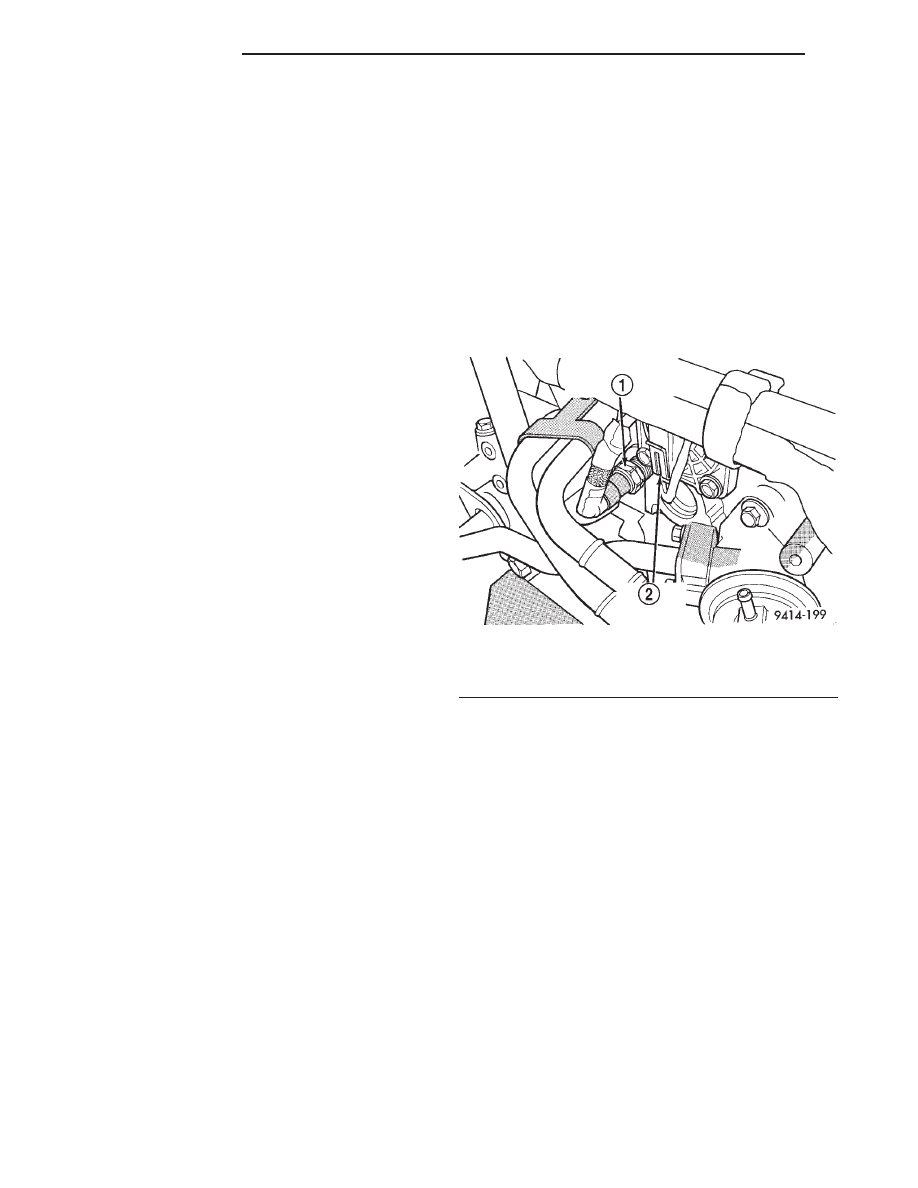
The coolant sensor threads into the rear of the cyl-
inder head on the 2.0L (Fig. 1). New sensors have
sealant applied to the threads.
OPERATION
The PCM determines engine coolant temperature
from the coolant temperature sensor. The ECT sensor
is a two wire Negative Thermal Coefficient (NTC)
sensor. The PCM sends 5 volts to the sensor and is
grounded through the sensor return line. As temper-
ature increases, resistance in the sensor decreases.
As coolant temperature varies, the coolant tempera-
ture sensor resistance changes resulting in a differ-
ent voltage value at the PCM engine coolant sense
circuit.
The coolant temperature sensor has one element.
The element supplies coolant temperature signal to
the PCM. The PCM supplies coolant temperature
information on the CCD Bus to the Body Control
Module (BCM) for the instrument panel gauge clus-
ter.
When the engine is cold, the PCM will provide
slightly richer air-fuel mixtures and higher idle
speeds until normal operating temperatures are
reached.
Fig. 1 Engine Coolant Temperature Sensor—2.0L
1 – ENGINE COOLANT TEMPERATURE SENSOR
2 – CAMSHAFT POSITION SENSOR
14 - 26
FUEL SYSTEM
JX
DESCRIPTION AND OPERATION (Continued)
HEATED OXYGEN SENSORS—PCM INPUT
DESCRIPTION
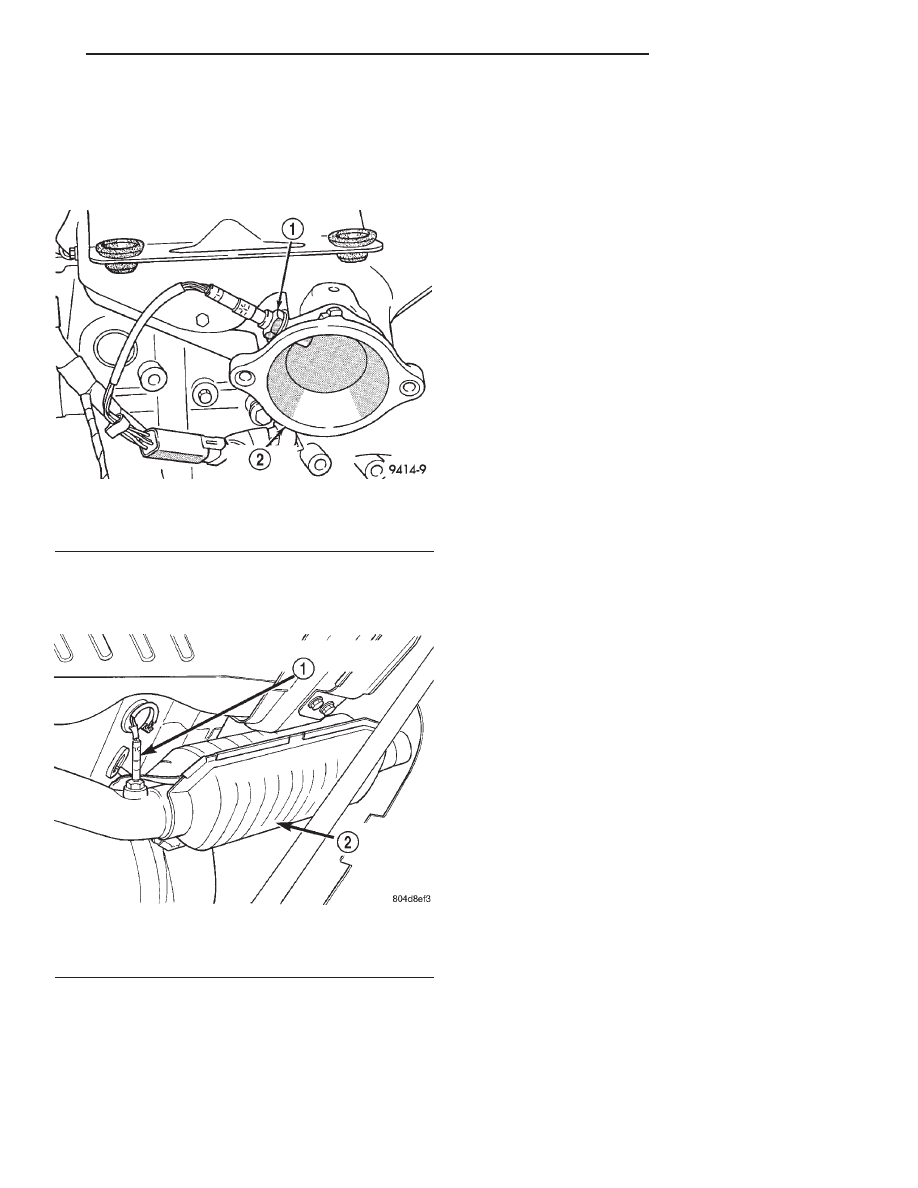
The upstream oxygen sensor threads into the out-
let flange of the exhaust manifold (Fig. 2).
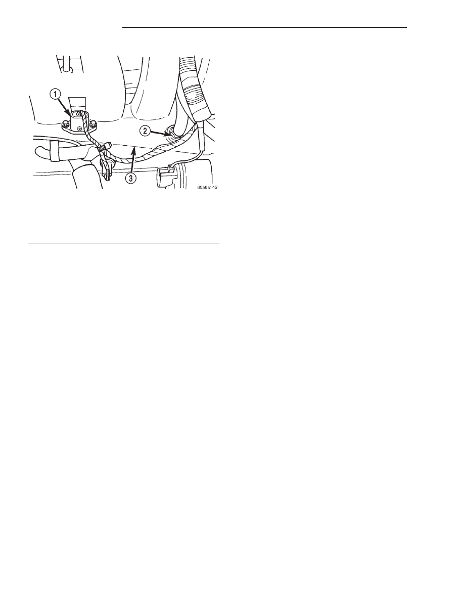
The downstream heated oxygen sensor threads into
the outlet pipe at the rear of the catalytic convertor
(Fig. 3).
OPERATION
OXYGEN SENSOR 1/1 UPSTREAM
The O2 Sensors are zirconium dioxide, four wire
and heated. The heater uses two of the sensors’ four
wires. One is common ground, the other provides bat-
tery voltage to the heater from the ASD Relay. One of
the remaining wires is a sensor signal input to the
PCM. The fourth wire is signal ground. The input
from the upstream heated oxygen sensor tells the
PCM the oxygen content of the exhaust gas. Based
on this input, the PCM fine tunes the air-fuel ratio
by adjusting injector pulse width.
The sensor input switches from 0 to 1 volt, depend-
ing upon the oxygen content of the exhaust gas in
the exhaust manifold. When a large amount of oxy-
gen is present (caused by a lean air-fuel mixture), the
sensor produces voltage as low as 0.1 volt. When
there is a lesser amount of oxygen present (rich air-
fuel mixture) the sensor produces a voltage as high
as 1.0 volt. By monitoring the oxygen content and
converting it to electrical voltage, the sensor acts as
a rich-lean switch.
The heating element in the sensor provides heat to
the sensor ceramic element. Heating the sensor
allows the system to enter into closed loop operation
sooner. Also, it allows the system to remain in closed
loop operation during periods of extended idle.
In Closed Loop, the PCM adjusts injector pulse
width based on the upstream heated oxygen sensor
input along with other inputs. In Open Loop, the
PCM adjusts injector pulse width based on prepro-
grammed (fixed) values and inputs from other sen-
sors.
OXYGEN SENSOR 1/2 DOWNSTREAM
The downstream heated oxygen sensor input is
used to detect catalytic convertor deterioration. As
the convertor deteriorates, the input from the down-
stream sensor begins to match the upstream sensor
input except for a slight time delay. By comparing
the downstream heated oxygen sensor input to the
input from the upstream sensor, the PCM calculates
catalytic convertor efficiency.
IGNITION SENSE—PCM INPUT
OPERATION
The ignition sense input informs the Powertrain
Control Module (PCM) that the ignition switch is in
the crank or run position.
INTAKE AIR TEMPERATURE SENSOR—PCM
INPUT
DESCRIPTION
The IAT sensor and Manifold Absolute Pressure
(MAP) sensor are a combined sensor that attach to
the intake manifold (Fig. 4) for 2.0L engine.
OPERATION
The Intake Air Temperature (IAT) sensor measures
the temperature of the intake air as it enters the
Fig. 2 Oxygen Sensor 1/1 Upstream—2.0L Engines
1 – OXYGEN SENSORS
2 – EXHAUST MANIFOLD
Fig. 3 Oxygen Sensor 1/2 Downstream
1 – DOWNSTREAM HEATED OXYGEN SENSOR
2 – CATALYTIC CONVERTOR
JX
FUEL SYSTEM
14 - 27
DESCRIPTION AND OPERATION (Continued)
engine. The sensor supplies one of the inputs the
PCM uses to determine injector pulse width and
spark advance.
MANIFOLD ABSOLUTE PRESSURE (MAP)
SENSOR—PCM INPUT
DESCRIPTION
The MAP sensor mounts to the intake manifold
(Fig. 4).
OPERATION
The MAP serves as a PCM input, using a silicon
based sensing unit, to provide data on the manifold
vacuum that draws the air/fuel mixture into the com-
bustion chamber. The PCM requires this information
to determine injector pulse width and spark advance.
When MAP equals Barometric pressure, the pulse
width will be at maximum.
Also like the cam and crank sensors, a 5 volt ref-
erence is supplied from the PCM and returns a volt-
age
signal
to
the
PCM
that
reflects
manifold
pressure. The zero pressure reading is 0.5V and full
scale is 4.5V. For a pressure swing of 0 — 15 psi the
voltage changes 4.0V. The sensor is supplied a regu-
lated 4.8 to 5.1 volts to operate the sensor. Like the
cam and crank sensors ground is provided through
the sensor return circuit.
The MAP sensor input is the number one contrib-
utor to pulse width. The most important function of
the MAP sensor is to determine barometric pressure.
The PCM needs to know if the vehicle is at sea level
or is it in Denver at 5000 feet above sea level,
because the air density changes with altitude. It will
also help to correct for varying weather conditions. If
a hurricane was coming through the pressure would
be very, very low or there could be a real fair
weather, high pressure area. This is important
because as air pressure changes the barometric pres-
sure changes. Barometric pressure and altitude have
a direct inverse correlation, as altitude goes up baro-
metric goes down. The first thing that happens as
the key is rolled on, before reaching the crank posi-
tion, the PCM powers up, comes around and looks at
the MAP voltage, and based upon the voltage it sees,
it knows the current barometric pressure relative to
altitude. Once the engine starts, the PCM looks at
the voltage again, continuously every 12 milliseconds,
and compares the current voltage to what it was at
key on. The difference between current and what it
was at key on is manifold vacuum.
During key On (engine not running) the sensor
reads (updates) barometric pressure. A normal range
can be obtained by monitoring known good sensor in
you work area.
As the altitude increases the air becomes thinner
(less oxygen). If a vehicle is started and driven to a
very different altitude than where it was at key On
the barometric pressure needs to be updated. Any
time the PCM sees Wide Open throttle, based upon
TPS angle and RPM it will update barometric pres-
sure in the MAP memory cell. With periodic updates,
the PCM can make its calculations more effectively.
The PCM uses the MAP sensor to aid in calculat-
ing the following:
• Barometric pressure
• Engine load
• Manifold pressure
• Injector pulse-width
• Spark-advance programs
• Shift-point strategies (F4AC1 transmissions
only, via the CCD bus)
• Idle speed
• Decel fuel shutoff
The MAP sensor signal is provided from a single
piezoresistive element located in the center of a dia-
phragm. The element and diaphragm are both made
of silicone. As the pressures changes the diaphragm
moves causing the element to deflect which stresses
the silicone. When silicone is exposed to stress its
resistance changes. As manifold vacuum increases,
the MAP sensor input voltage decreases proportion-
ally. The sensor also contains electronics that condi-
tion
the
signal
and
provide
temperature
compensation.
The PCM recognizes a decrease in manifold pres-
sure by monitoring a decrease in voltage from the
reading stored in the barometric pressure memory
cell. The MAP sensor is a linear sensor; as pressure
changes, voltage changes proportionately. The range
Fig. 4 Intake Air Temperature Sensor and MAP
Sensor—2.0L
1 – MAP/AIR TEMPERATURE SENSOR
2 – PCV VACUUM NIPPLE
3 – INTAKE MANIFOLD
14 - 28
FUEL SYSTEM
JX
DESCRIPTION AND OPERATION (Continued)
Нет комментариевНе стесняйтесь поделиться с нами вашим ценным мнением.
Текст