
Chrysler Stratus Convertible. Manual — part 113
gauging for proper shims. Improperly seated bearing
cups and cones are subject to low–mileage failure.
(2) Bearing cups and cones should be replaced if
they show signs of pitting or heat distress. If distress
is seen on either the cup or bearing rollers, both cup
and cone must be replaced.
(3) Bearing preload and drag torque specifications
must be maintained to avoid premature bearing fail-
ures. Used (original) bearings may lose up to 50% of
their original drag torque after break in. All bearing
adjustments must be made with no other component
interference or gear intermesh.
(4) Replace bearings as a pair: If one differential
bearing is defective, replace both differential bear-
ings, if one input shaft bearing is defective, replace
both input shaft bearings.
(5) Bearing cones must not be reused if removed.
(6) Turning torque readings should be obtained
while smoothly rotating in either direction.
DIFFERENTIAL BEARING PRELOAD
ADJUSTMENT
NOTE: True bearing turning torque readings can be
obtained only with the geartrain removed from the
case.
(1) Remove bearing cup and existing shim from
clutch bellhousing case.
(2) Press in new bearing cup into bellhousing case
(or use a cup that has been ground down on the
outer edge for ease of measurement).
(3) Press in new bearing cup into gear case side.
(4) Oil differential bearings with Mopar
t type M.
S. 9417 Manual Transaxle Fluid. Install differential
assembly in transaxle gear case. Install clutch bell-
housing over gear case. Install and torque case bolts
to 29 N·m (21 ft. lbs.).
(5) Position
transaxle
with
bellhousing
facing
down on workbench with C-clamps. Position dial
indicator.
(6) Apply a medium load to differential with Tool
C-4995 and a T-handle, in the downward direction.
Roll differential assembly back and forth a number of
times. This will settle the bearings. Zero the dial
indicator. To obtain end play readings, apply a
medium load in an upward direction while rolling
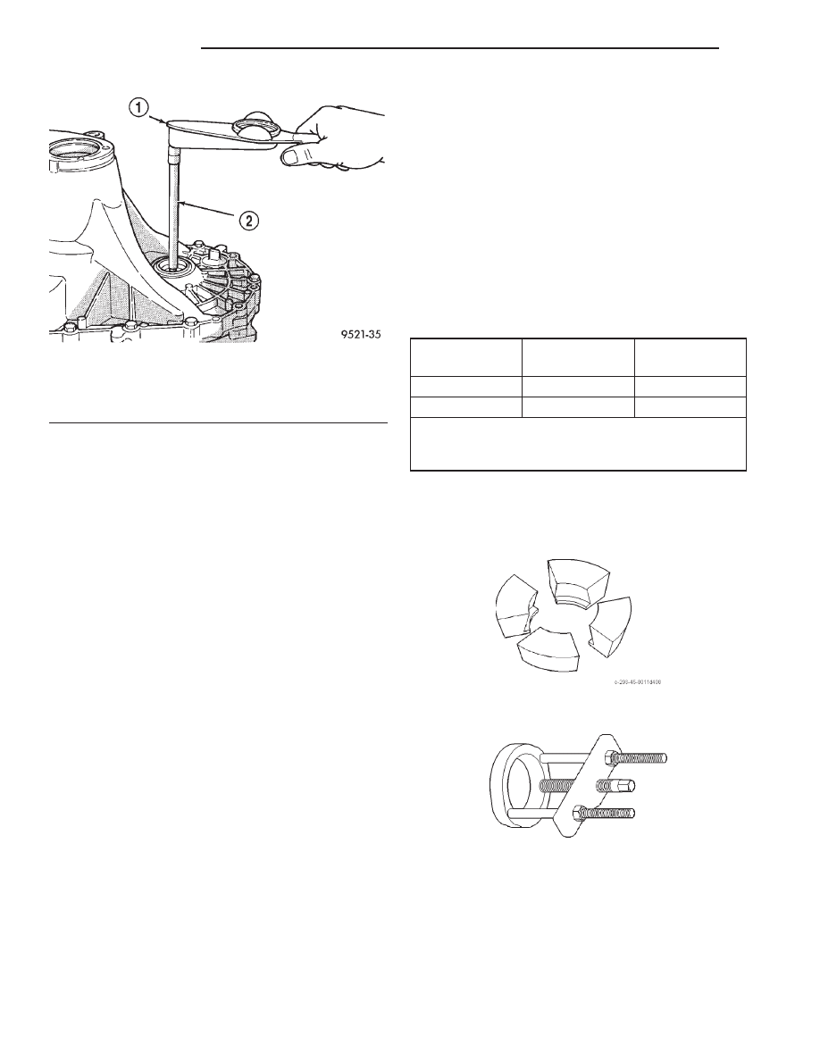
differential assembly back and forth (Fig. 145).
Record end play.
(7) The shim required for proper bearing preload is
the total of end play, plus (constant) preload of
0.18mm (0.007 in.). Never combine shims to obtain
the required preload.
(8) Remove case bolts. Remove clutch bellhousing
differential bearing cup. Install shim(s) selected in
Step 7. Then press the bearing cup into clutch bell-
housing.
(9) Install clutch bellhousing. Install and torque
case bolts to 26 N·m (19 ft. lbs.).
(10) Using Special Tool C-4995 and an inch-pound
torque wrench, check turning torque of the differen-
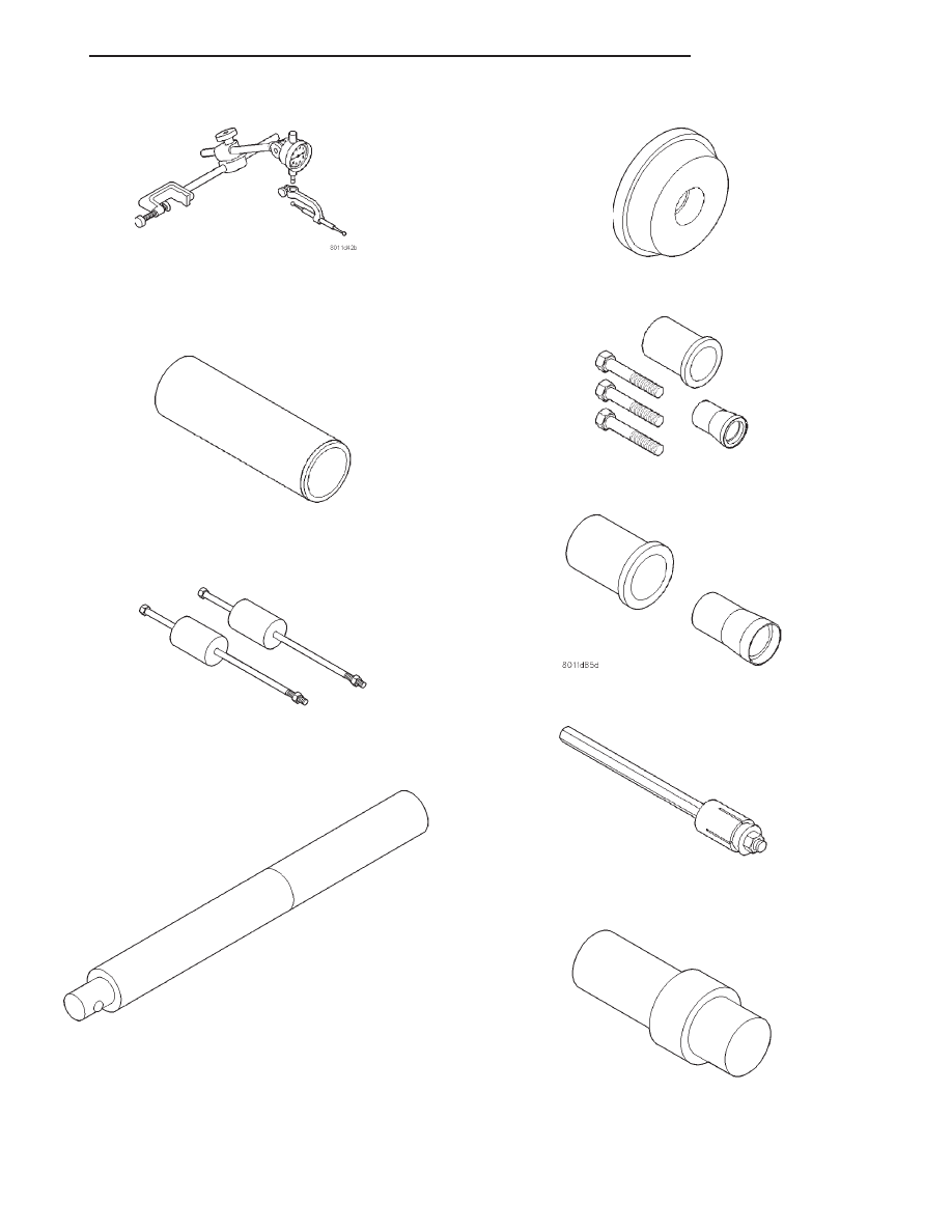
tial assembly (Fig. 146). The turning torque
should be 6 to 12 in. lbs. If the turning torque is
too high, install a 0.05mm (0.002 inch) thinner
shim. If the turning torque is too low, install a
0.05mm (0.002 inch) thicker shim.
(11) Recheck turning torque. Repeat Step 10 until
the proper turning torque is obtained.
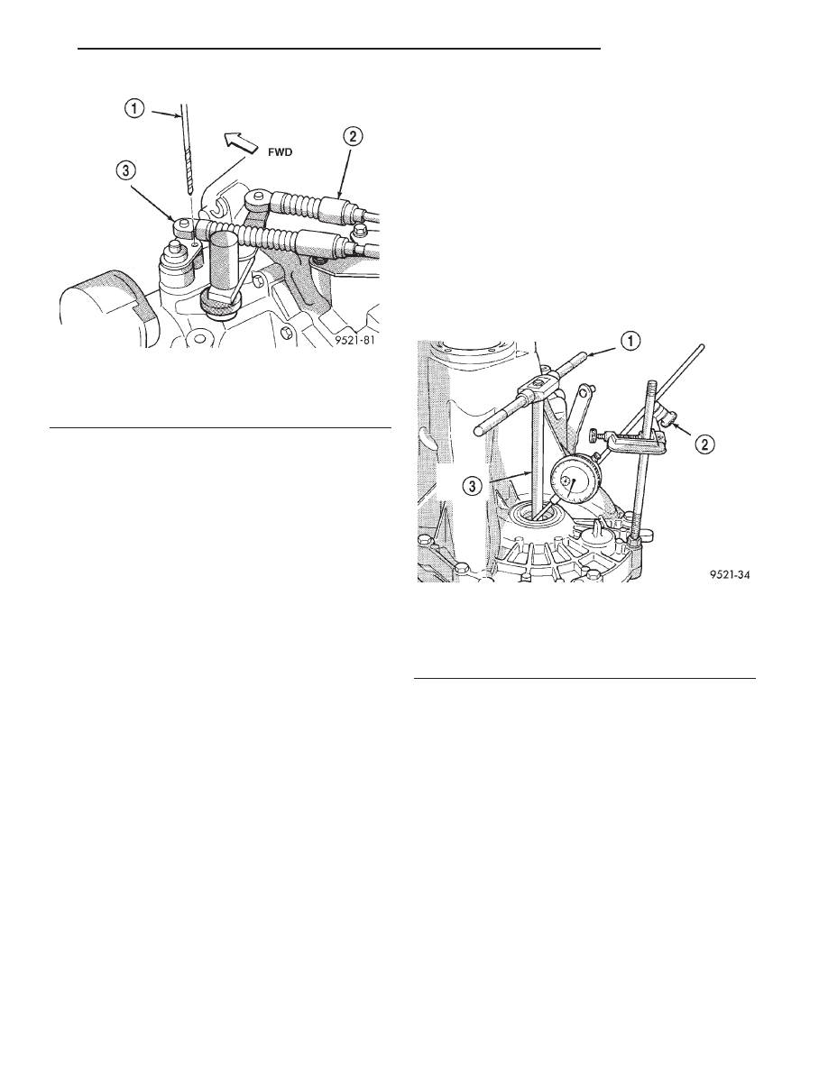
Fig. 144 Crossover Lever Pin Procedure
1 –
1
⁄
4
88
DRILL BIT
2 – SELECTOR CABLE
3 – CROSSOVER CABLE
Fig. 145 Checking Differential Bearing End Play to
Determine Shim Thickness
1 – T-HANDLE
2 – DIAL INDICATOR SET
3 – SPECIAL TOOL C-4995
JX
TRANSAXLE
21 - 43
ADJUSTMENTS (Continued)
SPECIFICATIONS
NV T350 (A-578)
DESCRIPTION
TORQUE
Back-up Lamp Switch . . . . . . . . 24 N·m (18 ft. lbs.)
Crossover Cable Adj. Screw . . . . 8 N·m (70 in. lbs.)
Drain Plug . . . . . . . . . . . . . . . 30 N·m (267 in. lbs.)
Differential Ring Gear Bolts . . . 81 N·m (60 ft. lbs.)
Dust Shield to Transaxle . . . . 12 N·m (105 in. lbs.)
End Plate Cover Bolts . . . . . . . . 29 N·m (21 ft. lbs.)
Front Engine Mount to Trans . 108 N·m (80 ft. lbs.)
Front Mount Through Bolt . . . . 61 N·m (45 ft. lbs.)
Front Mount to Engine Bolt . . . 54 N·m (40 ft. lbs.)
Lateral Bending Strut to Engine . . . . . . . . . 54 N·m
(40 ft. lbs.)
Lateral Bending Strut to Trans. . . . . . . . . . 54 N·m
(40 ft. lbs.)
Left Mount Through Bolt . . . . 108 N·m (80 ft. lbs.)
Left Mount to Transaxle . . . . . . 54 N·m (40 ft. lbs.)
Output Bearing Race Ret. Strap . . . . . . . . . 11 N·m
(96 in. lbs.)
Power Hop Damper Bkt. to Trans. . . . . . . . 54 N·m
(40 ft. lbs.)
Power Hop Damper to Frame Bkt. . . . . . . . 54 N·m
(40 ft. lbs.)
Power Hop Damper to Trans. Bkt. . . . . . . . 54 N·m
(40 ft. lbs.)
Reverse Fork Bracket . . . . . . . . 11 N·m (96 in. lbs.)
Reverse Idler Shaft Bolt . . . . . . 26 N·m (19 ft. lbs.)
Shift Cable Bracket to Transaxle . . . . . . . . 28 N·m
(250 in. lbs.)
Transaxle Case Bolts . . . . . . . . . 29 N·m (21 ft. lbs.)
Transaxle to Engine Bolt . . . . . . 95 N·m (70 ft. lbs.)
DESCRIPTION
TORQUE
Trans. to Eng. Intake Bkt. Bolts . . . . . . . . . 95 N·m
(70 ft. lbs.)
Vehicle Speed Sensor . . . . . . . . . 7 N·m (60 in. lbs.)
Vertical Bending Strut to Engine . . . . . . . 108 N·m
(80 ft. lbs.)
Vertical Bending Strut to Trans. . . . . . . . . 108 N·m
(80 ft. lbs.)
NOTE: Bolts that have thread sealer or torque lock
patches should not be reused. Always install new
bolts in these applications.
SPECIAL TOOLS
NV T350 (A-578) MANUAL TRANSAXLE
Fig. 146 Checking Differential Bearing Turning
Torque
1 – INCH-POUND TORQUE WRENCH
2 – SPECIAL TOOL C-4995
NV T350 (A-578) MANUAL TRANSAXLE FLUID
FILL
TRANSAXLE
METRIC
MEASURE
U. S.
MEASURE
NV T350
1.9-2.2 Liters
2.0-2.3 Quarts
NV T350HD
2.4-2.7 Liters
2.5-2.8 Quarts
NOTE: Two 5 speed transaxles are available. Refer
to capacity label on case near left driveshaft for
identification.
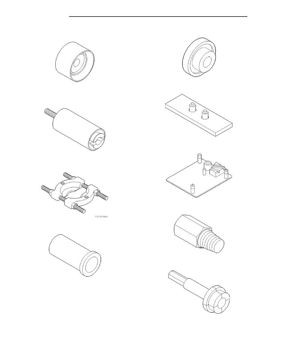
Adapter Blocks C-293–45
Puller Press C-293–PA
21 - 44
TRANSAXLE
JX
ADJUSTMENTS (Continued)
Dial Indicator C-3339
Sleeve C-3717
Slide Hammer C-3752
Universal Handle C-4171
Bearing Installer C-4628
Seal Remover C-4680
Seal Installer C-4992
Torque Tool C-4995
Adapter C-4996
JX
TRANSAXLE
21 - 45
SPECIAL TOOLS (Continued)
Installer L-4410
Special Jaw Set L-4518
Bearing Splitter 1130
Driver 6342
Seal Installer 6709
Bearing Remover 6768
Bench Fixture 6785
Remover 6786
Remover 6787
21 - 46
TRANSAXLE
JX
SPECIAL TOOLS (Continued)
Нет комментариевНе стесняйтесь поделиться с нами вашим ценным мнением.
Текст