
Chrysler Stratus Convertible. Manual — part 112
DIFFERENTIAL BEARING CUPS
REMOVAL
(1) Remove differential assembly from gear case
using the procedure outlined in this group.
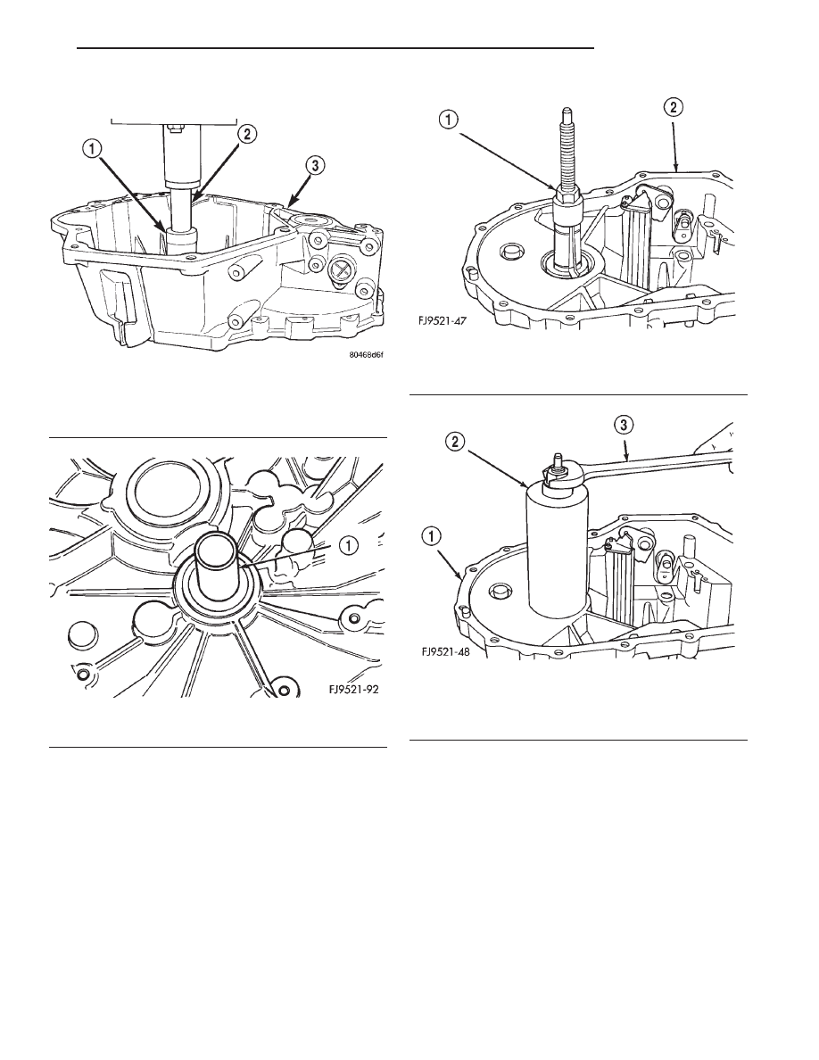
(2) Install Miller tool #L-4518 into the differential
bearing cup (Fig. 134).
(3) Install the tool cup over the tool (Fig. 135).
(4) Tighten the tool until the race is removed from
the case.
INSTALLATION
(1) Position the bearing cup into the case.
(2) Install
the
bearing
cup
onto
Miller
tool
#L-4520.
(3) Using Miller tool #L-4520 and C-4171 driver,
install differential bearing cup into the transaxle
case.
SHIFT RAIL BUSHINGS
REMOVAL
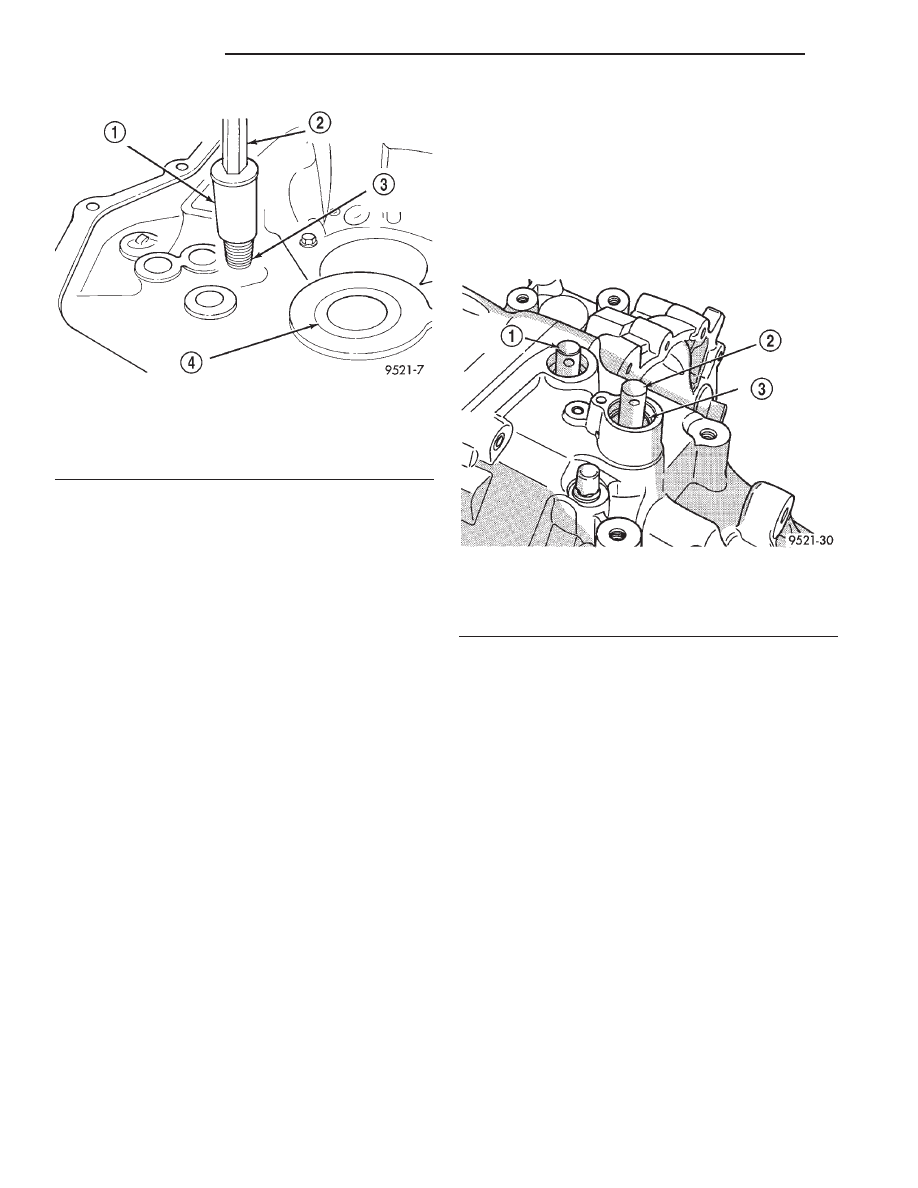
(1) Thread tool #6786 into shift rail bushing.
(2) Install slide hammer #3752 onto tool.
(3) Remove bushing using slide hammer and tool
assembly (Fig. 136).
Fig. 132 Input Bearing Tool
1 – SPECIAL TOOL C-4680-1
2 – SPECIAL TOOL 4894
3 – BELLHOUSING HALF
Fig. 133 Input Bearing Installed
1 – SLEEVE AND BEARING ASSEMBLY
Fig. 134 Tool Installed in Bearing
1 – SPECIAL TOOL L-4518
2 – GEAR CASE
Fig. 135 Tool Cup Installed
1 – GEAR CASE
2 – SPECIAL TOOL L-4518
3 – WRENCH
JX
TRANSAXLE
21 - 39
DISASSEMBLY AND ASSEMBLY (Continued)
INSTALLATION
(1) Line up replacement bushing in bore.
(2) Using tool #MD998343, tap bushing into bore
until flush with the chamfer in the case.
SHIFT SHAFT SEALS
It is not necessary to remove the shift shafts from
the transaxle to service the shift shaft seals.
REMOVAL
(1) Using a pick tool, pry up on the shift shaft seal
and remove seal from bore.
INSTALLATION
(1) Position new shift shaft seal in bore.
(2) Install shift shaft seal into bore using an
appropriate size deep-well socket.
SHIFT SELECTOR SHAFT
REMOVAL
(1) Disassemble transaxle using the procedure out-
lined in this group.
(2) With the transaxle disassembled, remove the
selector shaft by pushing on the shaft from the out-
side. Pull shaft out from the inside.
INSTALLATION
(1) Reverse removal procedure to install selector
shaft.
SHIFT CROSSOVER SHAFT
REMOVAL
(1) Disassemble transaxle using the procedure out-
lined in this group.
(2) With the transaxle disassembled, remove the
crossover shaft seal.
(3) Using snap–ring pliers, remove the snap ring
at the crossover shaft bore (Fig. 137).
(4) Push the crossover shaft in the case and
remove the crossover assembly.
INSTALLATION
(1) Reverse removal procedure to install crossover
shaft.
SHIFT SELECTOR SHAFT BUSHING
REMOVAL
(1) Remove selector shaft using procedure in this
group.
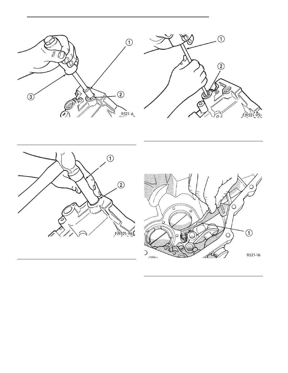
(2) Thread tool #6786 into bushing.
(3) Install slide hammer #3752 onto tool and
remove bushing using slide hammer (Fig. 138).
INSTALLATION
(1) Position replacement bushing over selector
shaft bore.
(2) Using an appropriate size deep–well socket,
install bushing in selector shaft bore (Fig. 139).
Fig. 136 Shift Rail Bushing Removal
1 – SPECIAL TOOL 6786
2 – SLIDE HAMMER C-3752
3 – SHIFTER RAIL BUSHING
4 – INPUT BEARING
Fig. 137 Crossover Shaft Snap Ring
1 – SELECTOR SHAFT
2 – CROSSOVER SHAFT
3 – SNAP RING
21 - 40
TRANSAXLE
JX
DISASSEMBLY AND ASSEMBLY (Continued)
SHIFT CROSSOVER SHAFT BUSHING
REMOVAL
(1) Install slide hammer #3752 through the cross-
over bushing.
(2) Thread nut and washer onto slide hammer.
(3) Using the slide hammer, remove the crossover
shaft bushing (Fig. 140).
INSTALLATION
(1) Position the replacement crossover shaft bush-
ing over the crossover shaft bushing bore.
(2) Using an appropriate size deep–well socket,
install the crossover shaft bushing into the bushing
bore.
REAR BEARING OIL FEED TROUGH
The bearing oil feed trough is retained in the case
by a pin that is molded into the case and clips that
are part of the trough (Fig. 141).
REMOVAL
(1) Using light plier pressure, squeeze the clips
together at the rear of the trough.
(2) Slide the trough over the retaining pin that
locates the trough in the case.
INSTALLATION
(1) Reverse removal procedure to install oil feed
trough.
Fig. 138 Selector Shaft Bushing Removal
1 – SPECIAL TOOL 6786
2 – SHIFT SHAFT BUSHING
3 – SLIDE HAMMER C-3752
Fig. 139 Selector Shaft Bushing Installation
1 – DEEP WELL SOCKET
2 – SHIFTER SHAFT BUSHING
Fig. 140 Crossover Shaft Bushing Removal
1 – SLIDE HAMMER
2 – SHIFTER SHAFT BUSHING
Fig. 141 Oil Feed Trough
1 – OIL FEED TROUGH
JX
TRANSAXLE
21 - 41
DISASSEMBLY AND ASSEMBLY (Continued)
CLEANING AND INSPECTION
TRANSAXLE
Clean the gears, bearings, shafts, synchronizers,
thrust washers, oil feeder, shift mechanism, gear
case, and bellhousing with solvent. Dry all parts
except the bearings with compressed air. Allow the
bearings to either air dry or wipe them dry with
clean shop towels.
Inspect the gears, bearings, shafts and thrust
washers. Replace the bearings and cups if the rollers
are worn, chipped, cracked, flat spotted, or brin-
nelled, or if the bearing cage is damaged or distorted.
Replace the thrust washers if cracked, chipped, or
worn. Replace the gears if the teeth are chipped,
cracked, or worn thin. Inspect the synchronizers.
Replace the sleeve if worn or damaged in any way.
Replace the stop rings if the friction material is
burned, flaking off, or worn. Check the condition of
the synchro keys and springs. Replace these parts if
worn, cracked, or distorted.
SYNCHRONIZER
CLEAN
Do not attempt to clean the blocking rings in sol-
vent. The friction material will become contaminated.
Place synchronizer components in a suitable holder
and clean with solvent. Air dry.
INSPECT
Proper inspection of components involve:
• Teeth, for wear, scuffed, nicked, burred, or bro-
ken teeth
• Keys, for wear or distortion
• Balls and springs, for distortion, cracks, or wear
If any of these conditions exist in these compo-
nents, replace as necessary.
ADJUSTMENTS
GEARSHIFT CROSSOVER CABLE ADJUSTMENT
(1) Remove shift console from vehicle.
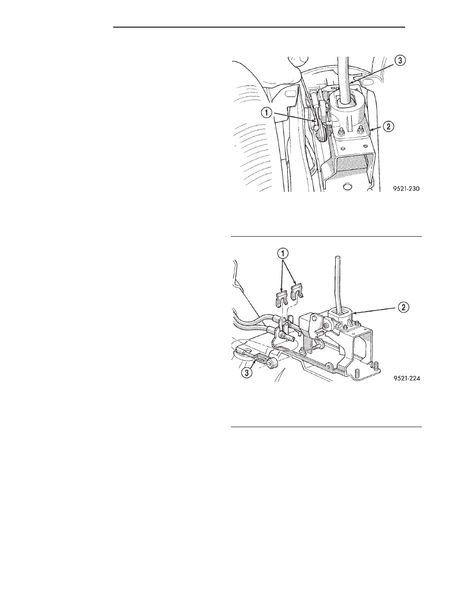
(2) Loosen adjusting screw on crossover cable at
shifter (Fig. 142) (Fig. 143).
(3) Pin transaxle crossover lever in 3-4 neutral
position using a 1/4 inch drill bit. Align hole in cross-
over lever with the hole in the boss on the transaxle
case (Fig. 144). Make sure drill bit goes into tran-
saxle case at least one half inch.
(4) The shifter is spring loaded and self centering.
Allow shifter to rest in its neutral position. Torque
adjustment screw to 8 N·m (70 in. lbs.). Care must be
taken to avoid moving the shift mechanism off-center
during screw tightening.
(5) Remove drill bit from transaxle case and per-
form functional check by shifting transaxle into all
gears.
(6) Reinstall console. Reinstall boot and knob.
BEARING ADJUSTMENT PROCEDURE
GENERAL RULES ON SERVICING BEARINGS
(1) Use extreme care when removing and install-
ing bearing cups and cones. Use only an arbor press
for installation, as a hammer may not properly align
the bearing cup or cone. Burrs or nicks on the bear-
ing seat will give a false end play reading while
Fig. 142 Loosen Crossover Cable Adjustment Screw
1 – CROSSOVER CABLE ADJUSTMENT
2 – SHIFTER MECHANISM
3 – SHIFTER HANDLE
Fig. 143 Crossover Cable Adjustment Screw
1 – CABLE CLIPS
2 – SHIFTER
3 – ADJUSTMENT SCREW
21 - 42
TRANSAXLE
JX
Нет комментариевНе стесняйтесь поделиться с нами вашим ценным мнением.
Текст