
Chrysler Stratus Convertible. Manual — part 95
(1) Install transaxle solenoid pack and new gasket
(Fig. 369).
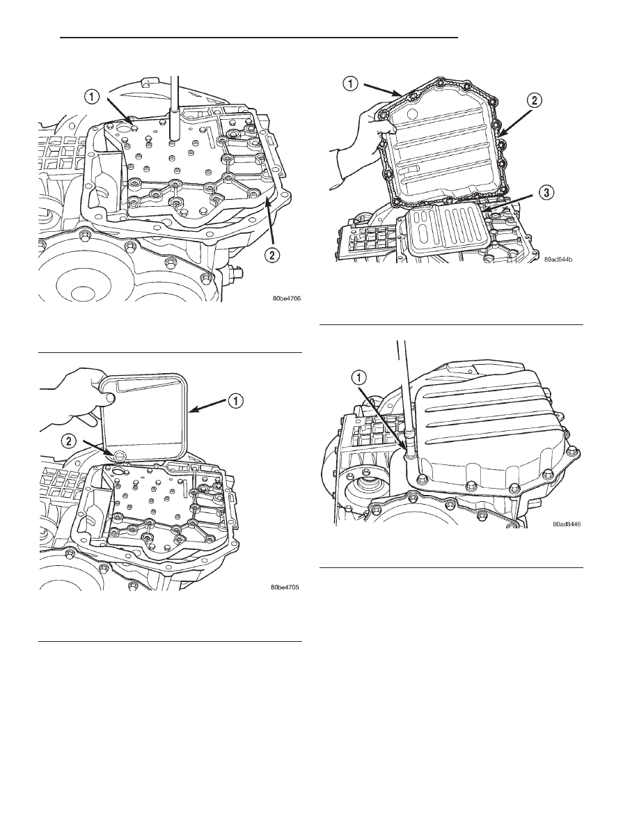
Fig. 365 Install Valve Body Attaching Bolts
1 – VALVE BODY ATTACHING BOLTS (18)
2 – VALVE BODY
Fig. 366 Install Oil Filter and New O-Ring
1 – OIL FILTER
2 – O-RING
Fig. 367 Install Oil Pan
1 – OIL PAN
2 – 1/8 INCH BEAD OF RTV SEALANT
3 – OIL FILTER
Fig. 368 Install Pan Bolts
1 – OIL PAN BOLTS (USE RTV UNDER BOLT HEADS)
JX
TRANSAXLE
21 - 119
DISASSEMBLY AND ASSEMBLY (Continued)
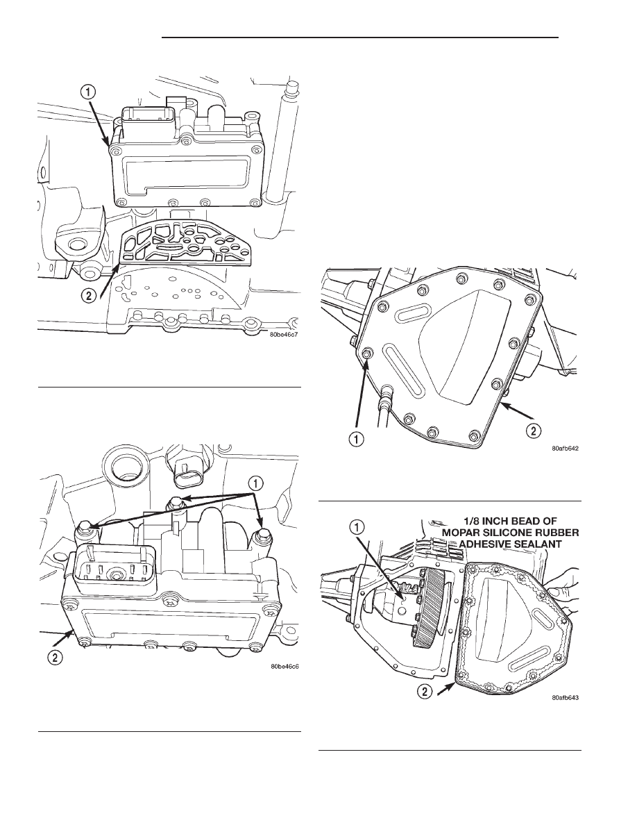
(2) Install and tighten solenoid/pressure switch
assembly-to-transaxle case bolts to 12 N·m (110 in.)
lbs.) torque (Fig. 370).
(3) Install input and output speed sensors.
DIFFERENTIAL REPAIR
NOTE: The differential is serviced as an assembly.
The only parts that are serviceable within the differ-
ential are the differential bearing cups and cones. If
any other part fails within the differential, you must
replace the differential assembly along with the
transfer shaft.
DISASSEMBLY
The transfer shaft should be removed for differen-
tial repair and bearing turning torque checking.
(1) Remove the differential cover and bolts (Fig.
371) (Fig. 372).
Fig. 369 Install Solenoid Pack
1 – SOLENOID/PRESSURE SWITCH ASSEMBLY
2 – GASKET
Fig. 370 Solenoid/Pressure Switch Assembly-to-
Case Mounting Bolts
1 – BOLTS
2 – SOLENOID AND PRESSURE SWITCH ASSEMBLY
Fig. 371 Differential Cover Bolts
1 – DIFFERENTIAL COVER BOLTS
2 – DIFFERENTIAL COVER
Fig. 372 Remove Differential Cover
1 – DIFFERENTIAL ASSEMBLY
2 – DIFFERENTIAL COVER
21 - 120
TRANSAXLE
JX
DISASSEMBLY AND ASSEMBLY (Continued)
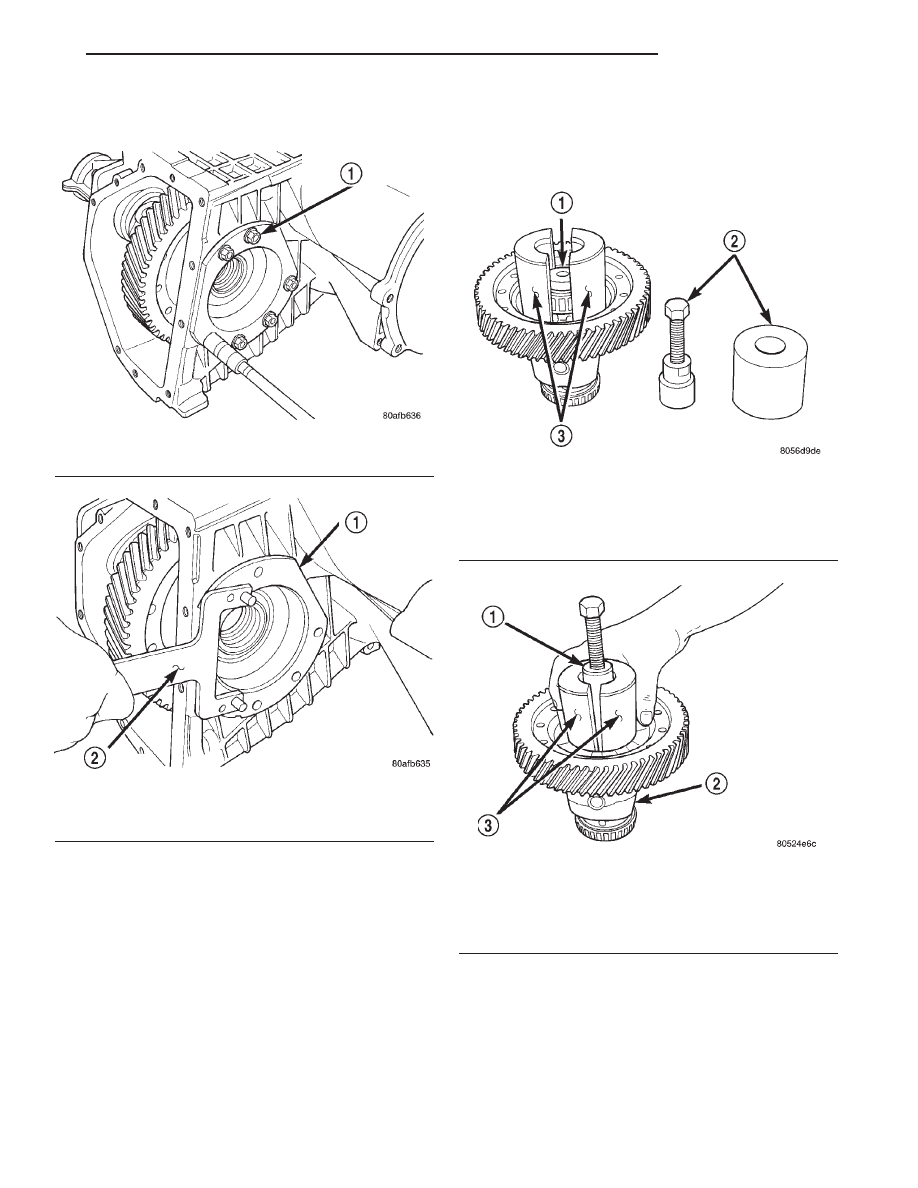
(2) Remove the differential bearing retainer and
bolts (Fig. 373) (Fig. 374).
(3) Using a plastic hammer, remove extension
housing/adapter plate on the right side of the tran-
saxle.
WARNING: HOLD ONTO DIFFERENTIAL ASSEMBLY
TO PREVENT IT FROM ROLLING OUT OF HOUSING.
(4) Use Miller Special Tool 5048, 5048-3 Collets,
and L-4539-2 Button to remove the differential bear-
ing cone on the extension housing side.
(5) Use Miller Special Tool 5048, 5048-4 Collets,
and L-4539-2 Button to remove the differential bear-
ing cone on the bearing retainer side (Fig. 375) (Fig.
376) (Fig. 377).
Fig. 373 Differential Retainer Bolts
1 – DIFFERENTIAL RETAINER BOLTS
Fig. 374 Remove Bearing Retainer
1 – DIFFERENTIAL BEARING RETAINER
2 – TOOL L-4435
Fig. 375 Position Button and Collets Onto
Differential and Bearing (Ring Gear Side)
1 – SPECIAL TOOL L-4539-2
2 – SPECIAL TOOL 5048
3 – SPECIAL TOOL 5048-4
Fig. 376 Position Tool 5048 Over Button and Collets
at Differential Bearing (Ring Gear Side)
1 – SPECIAL TO0L 5048
2 – DIFFERENTIAL
3 – SPECIAL TOOL 5048-4
JX
TRANSAXLE
21 - 121
DISASSEMBLY AND ASSEMBLY (Continued)
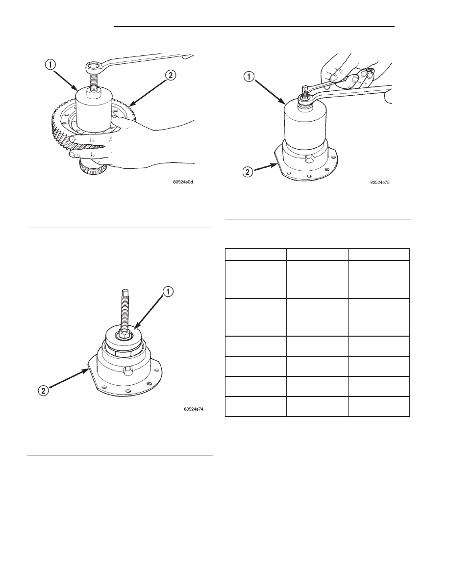
(6) Using Miller Special Tool L-4518, remove the
differential bearing race from the extension housing.
(7) Using Miller Special Tool 6062A, remove the
differential bearing race from the bearing retainer
(Fig. 378) (Fig. 379).
CHECKING SIDE GEAR END PLAY
Check side gear end play whenever the differential
is removed for service.
Fig. 377 Remove Differential Bearing Cone (Ring
Gear Side)
1 – SPECIAL TOOL 5048
2 – RING GEAR
Fig. 378 Position Bearing Cup Remover Tool in
Retainer
1 – SPECIAL TOOL 6062A
2 – DIFFERENTIAL BEARING RETAINER
Fig. 379 Remove Bearing Cup
1 – SPECIAL TOOL 6062A
2 – DIFFERENTIAL BEARING RETAINER
DIFFERENTIAL SERVICE TOOLS
COMPONENT
REMOVER
INSTALLER
Diff. Bear. On
Retainer Side
5048, 5048-4
Collets,
L-4539-2
Button
5052, C-4171
Diff. Bear. On
Ext. Hous. Side
5048, 5048-3
Collets,
L-4539-2
Button
L-4410, C-4171
Diff. Race. On
Retainer Side
6062-A
6061, C-4171
Diff. Race. On
Ext. Hous. Side
L-4518
L-4520, C-4171
Extension
Housing Seal
7794-A, C-637
Slide Hammer
L-4520, C-4171
Bearing
Retainer Seal
794-A, C-637
Slide Hammer
L-4520, C-4171
21 - 122
TRANSAXLE
JX
DISASSEMBLY AND ASSEMBLY (Continued)
Нет комментариевНе стесняйтесь поделиться с нами вашим ценным мнением.
Текст