
Chrysler Stratus Convertible. Manual — part 96
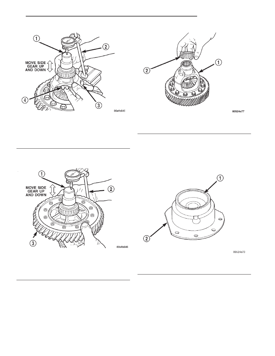
NOTE: Side gear end play must be BETWEEN 0.001
to 0.013 inch.
ASSEMBLY
NOTE: Use Mopar
T
Silicone Rubber Adhesive Seal-
ant, or equivalent, on retainer and extension hous-
ing/adapter plate to seal to case.
(1) Using Miller Special Tool L-4410, and C-4171,
install differential bearing to differential (extension
housing side) (Fig. 382).
(2) Using Miller Special Tool 5052 and C-4171,
install differential bearing to differential (bearing
retainer side).
(3) Using Miller Special Tool 6061 and C-4171,
install differential bearing race to bearing retainer
(Fig. 383).
(4) Using Miller Special Tool L–4520 and C-4171,
install differential bearing to extension housing.
DIFFERENTIAL BEARING PRELOAD ADJUSTMENT
NOTE: Perform all differential bearing preload mea-
surements
with
the
transfer
shaft
and
gear
removed.
Fig. 380 Checking Side Gear End Play (Extension
Housing Side)
1 – SPECIAL TOOL C-4996 (NOTE POSITION)
2 – DIAL INDICATOR SET
3 – DIFFERENTIAL ASSEMBLY
4 – SIDE GEAR
Fig. 381 Checking Side Gear End Play (Bearing
Retainer Side)
1 – SPECIAL TOOL C-4996 (NOTE POSITION)
2 – DIAL INDICATOR SET
3 – DIFFERENTIAL ASSEMBLY
Fig. 382 Position Bearing Cone Onto Differential
1 – DIFFERENTIAL ASSEMBLY
2 – DIFFERENTIAL BEARING
Fig. 383 Differential Bearing Retainer
1 – DIFFERENTIAL BEARING CUP
2 – DIFFERENTIAL BEARING RETAINER
JX
TRANSAXLE
21 - 123
DISASSEMBLY AND ASSEMBLY (Continued)
DIFFERENTIAL BEARING PRELOAD ADJUSTMENT USING
EXISTING SHIM
(1) Position the transaxle assembly vertically on
the support stand, differential bearing retainer side
up.
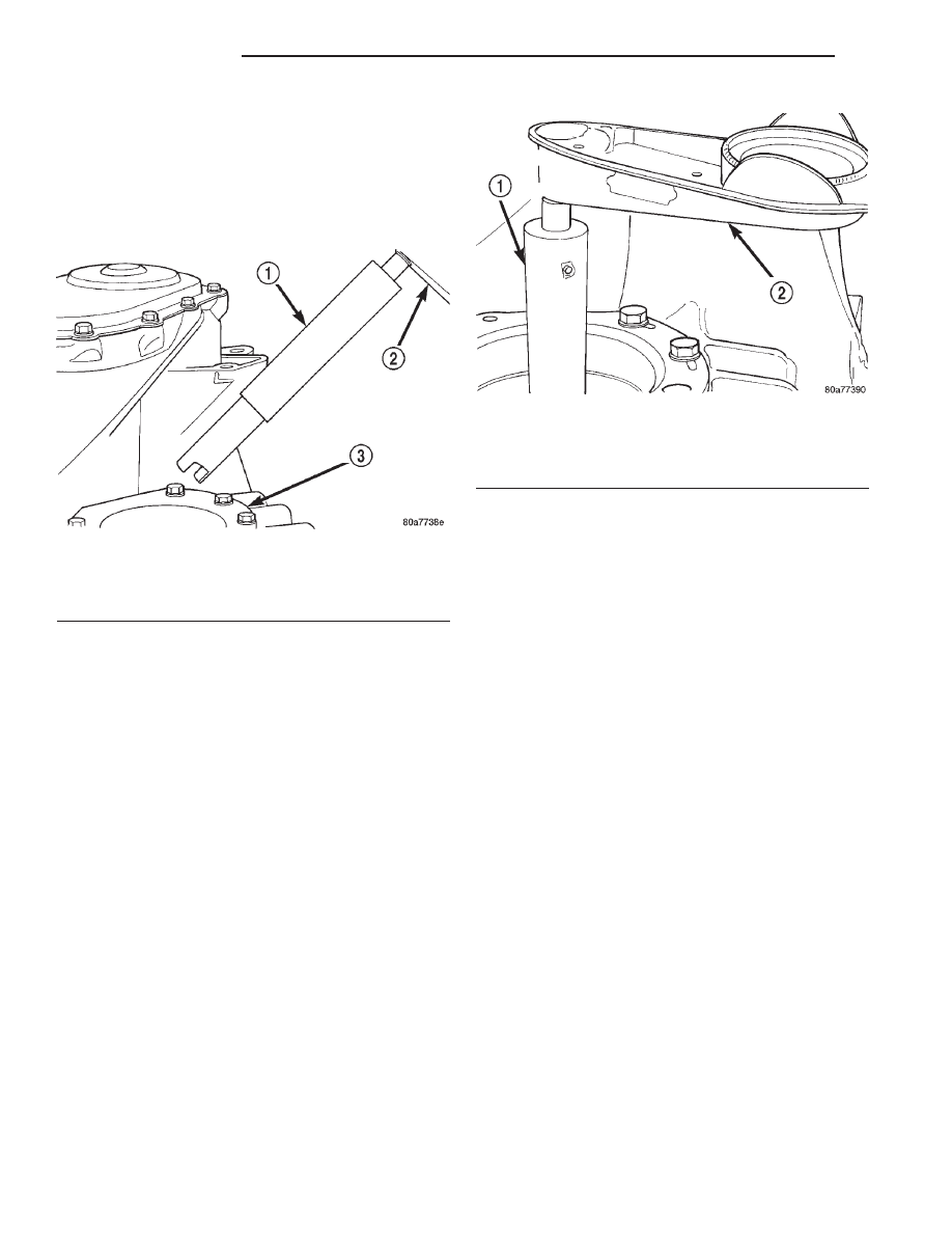
(2) Install Tool L-4436A into the differential and
onto the pinion mate shaft (Fig. 384).
(3) Rotate the differential at least one full revolu-
tion to ensure the tapered roller bearings are fully
seated.
(4) Using Tool L-4436A and an inch-pound torque
wrench, check the turning torque of the differential
(Fig.
385).
The
turning
torque
should
be
between 5 and 18 inch-pounds.
(5) If the turning torque is within specifications,
remove tools. Setup is complete.
(6) If turning torque is not within specifications
proceed with the following steps.
(a) Remove differential bearing retainer from
the transaxle case.
(b) Remove the bearing cup from the differential
bearing retainer using Tool 6062A.
(c) Remove the existing shim from under the
cup.
(d) Measure the existing shim.
(e) If the turning torque was too high when mea-
sured, install a.05 mm (.002 inch) thinner shim. If
the turning torque is was too low, install a.05 mm
(.002 inch) thicker shim. Repeat until 5 to 18 inch-
pounds turning torque is obtained. Oil Baffle is not
required to be installed when making shim selec-
tion.
(f) Install the proper shim under the bearing
cup. Make sure the oil baffle is installed properly
in the bearing retainer, below the bearing shim
and cup.
(g) Install the differential bearing retainer using
Tool 5052 and C-4171. Seal the retainer to the
housing with MOPAR
t Adhesive Sealant and
torque bolts to 28 N·m (250 in. lbs.).
(7) Using Tool L-4436A and an inch-pound torque
wrench, recheck the turning torque of the differential
(Fig.
385).
The
turning
torque
should
be
between 5 and 18 inch-pounds.
Shim thickness need be determined only if any of
the following parts are replaced:
• Transaxle case
• Differential carrier
• Differential bearing retainer
• Extension housing
• Differential bearing cups and cones
Fig. 384 Tool L-4436 and Torque Wrench
1 – SPECIAL TOOL L-4436–A
2 – TORQUE WRENCH
3 – DIFFERENTIAL BEARING RETAINER
Fig. 385 Checking Differential Bearings Turning
Torque
1 – SPECIAL TOOL L-4436–A
2 – TORQUE WRENCH
21 - 124
TRANSAXLE
JX
DISASSEMBLY AND ASSEMBLY (Continued)

DIFFERENTIAL BEARING SHIM CHART
PART NUMBER
SHIM THICKNESS
MM
INCH
4659257
.980
0.0386
4659258
1.02
0.0402
4659259
1.06
0.0418
4659260
1.10
0.0434
4659261
1.14
0.0449
4659262
1.18
0.0465
4659263
1.22
0.0481
4659264
1.26
0.0497
4659265
1.30
0.0512
4659266
1.34
0.0528
4659267
1.38
0.0544
4659268
1.42
0.0560
4659269
1.46
0.0575
4659270
1.50
0.0591
4659271
1.54
0.0607
4659272
1.58
0.0623
4659273
1.62
0.0638
4659274
1.66
0.0654
4659275
1.70
0.0670
4659283
2.02
0.0796
4659284
2.06
0.0812
PRELOAD ADJUSTMENT W/O SHIM
(1) Remove the bearing cup from the differential
bearing retainer using Miller special Tool 6062A.
(2) Remove existing shim from under bearing cup.
(3) Reinstall the bearing cup into the retainer
using Miller Special Tool 6061, and C-4171.
NOTE: Oil baffle is not required when making the
shim calculation.
(4) Install the bearing retainer into the case.
Torque bolts to 28 N
•m (250 in. lbs.).
(5) Position the transaxle assembly vertically on
the support stand and install Miller Special Tool
L-4436-A into the bearing retainer.
(6) Rotate the differential at least one full revolu-
tion to ensure the tapered roller bearings are fully
seated.
(7) Attach a dial indicator to the case and zero the
dial. Place the tip on the end of Special Tool
L-4436-A.
(8) Place a large screwdriver to each side of the
ring gear and lift. Check the dial indicator for the
amount of end play.
CAUTION: Do
not
damage
the
transaxle
case
and/or differential retainer sealing surface.
(9) Using the end play measurement that was
determined, add .18mm (.007 inch). This should give
you between 5 and 18 inch pounds of bearing pre-
load. Refer to the Differential Bearing Shim Chart to
determine which shim to use.
(10) Remove
the
differential
bearing
retainer.
Remove the bearing cup.
(11) Install the oil baffle. Install the proper shim
combination under the bearing cup.
(12) Install the differential bearing retainer. Seal
the retainer to the housing with Mopar
t Silicone
Rubber Adhesive Sealant. Torque bolts to 28 N
•m
(250 in. lbs.).
(13) Using Miller Special Tool L-4436-A and an
inch-pound torque wrench, check the turning torque
of the differential (Fig. 385). The turning torque
should be between 5-18 inch-pounds.
JX
TRANSAXLE
21 - 125
DISASSEMBLY AND ASSEMBLY (Continued)
NOTE: If turning torque is too high install a.05mm
(.002 inch) thicker shim. If the turning torque is too
low, install a.05mm (.002 inch) thinner shim. Repeat
until
5-18
inch-pounds
of
turning
torque
is
obtained.
CLEANING AND INSPECTION
CLEANING VALVE BODY
Prior to removing any transaxle parts, plug all
openings and clean unit, preferably by steam. Clean-
liness through entire disassembly and assembly can-
not be overemphasized. When disassembling, each
part should be washed in a suitable solvent, then
dried by compressed air. Do not wipe parts with
shop towels. All mating surfaces in the transaxles
are accurately machined; therefore, careful handling
of all parts must be exercised to avoid nicks or burrs.
NOTE: Tag all springs, as they are removed, for
reassembly identification.
ADJUSTMENTS
GEARSHIFT LINKAGE ADJUSTMENT
Normal operation of the Park/Neutral Position
Switch provides a quick check to confirm proper link-
age adjustment.
Move the selector level slowly forward until it
clicks into the (P) Park position. The starter should
operate.
After checking the (P) position, move selector
slowly toward the (N) Neutral position until lever is
in the (N) position. If the starter will also operate at
this point the gearshift linkage is properly adjusted.
If the starter fails to operate in either position, link-
age adjustment is required.
ADJUSTMENT
(1) Set parking brake.
(2) Remove the gearshift knob set screw and knob.
(3) Remove gearshift selector bezel and lamp wir-
ing.
(4) Install the gearshift knob set screw and knob.
(5) Place gearshift lever in the (P) (PARK) posi-
tion.
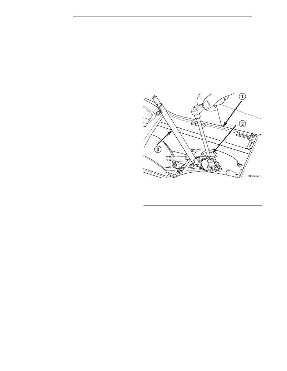
(6) Loosen the gearshift cable adjuster nut at the
shifter assembly (Fig. 386).
(7) Move the gearshift lever on the transaxle to
the park position.
(8) Verify the shift lever and transaxle are in park
position. Tighten the gearshift cable adjuster nut at
the shifter assembly. The gearshift linkage should
now be properly adjusted.
(9) Check adjustment as follows:
• Detent position for neutral and drive should be
within limits of hand lever gate stops.
• Key start must occur only when shift lever is in
park or neutral positions.
Fig. 386 Shift Cable Adjust Lever Nut
1 – CONSOLE
2 – ACCESS HOLE
3 – SHIFTER HANDLE
21 - 126
TRANSAXLE
JX
DISASSEMBLY AND ASSEMBLY (Continued)
Нет комментариевНе стесняйтесь поделиться с нами вашим ценным мнением.
Текст