
Chrysler Stratus Convertible. Manual — part 249
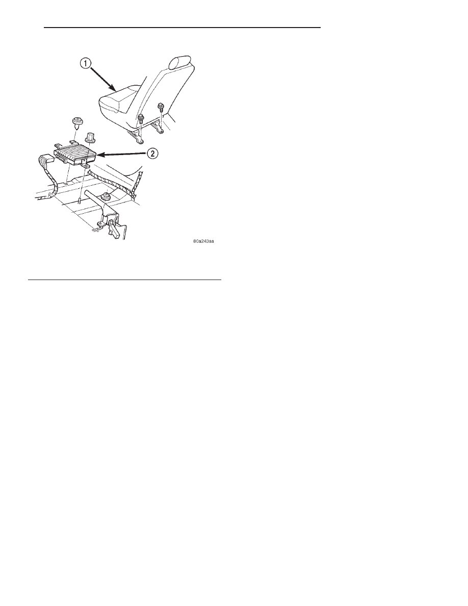
(4) Disconnect the electrical connector and remove
amplifier from vehicle.
INSTALLATION
(1) For installation, reverse the above procedures.
(2) Tighten amplifier screws to 4 N·m (40 in. lbs.)
torque.
(3) Push nut onto stud until seated.
(4) Reinstall front seat.
REMOTE CD CHANGER AND MOUNTING
BRACKET
REMOVAL
(1) Disconnect and isolate the battery negative
remote cable.
(2) Remove the instrument cluster hood. Refer to
Group
8E,
Instrument
Panel
and
Systems
for
Removal and Installation.
(3) Remove the two CD changer attaching screws
located under the HVAC control.
(4) Slide the CD changer/power outlet assembly
rearward in the vehicle.
(5) Disconnect CD cable, cigar lighter / power out-
let, and the light socket assembly wire connectors.
(6) Remove the CD changer and mounting bracket
from vehicle.
INSTALLATION
For installation, reverse the above procedures.
Fig. 11 Amplifier Location
1 – PASSENGER SEAT
2 – AMPLIFIER
JX
AUDIO SYSTEMS
8F - 17
REMOVAL AND INSTALLATION (Continued)
HORN SYSTEMS
TABLE OF CONTENTS
page
page
DESCRIPTION AND OPERATION
DIAGNOSIS AND TESTING
HORN . . . . . . . . . . . . . . . . . . . . . . . . . . . . . . . . . . 1
HORN CONTACT SWITCH . . . . . . . . . . . . . . . . . . 2
HORN RELAY . . . . . . . . . . . . . . . . . . . . . . . . . . . . 2
HORNS WILL NOT SOUND . . . . . . . . . . . . . . . . . 2
SYSTEM TEST . . . . . . . . . . . . . . . . . . . . . . . . . . . 3
REMOVAL AND INSTALLATION
DESCRIPTION AND OPERATION
HORN SYSTEM
WARNING: ON VEHICLES EQUIPPED WITH AIR-
BAG, SEE GROUP 8M, RESTRAINT SYSTEMS FOR
STEERING WHEEL OR COLUMN REMOVAL PROCE-
DURES.
DESCRIPTION
The horn circuit consists of a horn contact, horn
relay, and horns.
OPERATION
The horn circuit feed is from the fuse to the horn
relay in the Junction Block. When the horn contact is
depressed, it completes the ground circuit. Then the
horn relay coil closes a set of contacts which allows
current to flow to the horns. The horn(s) are
grounded at the shock tower. Refer to Group 8W,
Wiring Diagrams for horn circuit.
HORN RELAY
DESCRIPTION
The horn relay is a International Standards Orga-
nization (ISO) micro-relay. The terminal designations
and functions are the same as a conventional ISO
relay. However, the micro-relay terminal orientation
(or footprint) is different, current capacity is lower,
and the relay case dimensions are smaller than on
the conventional ISO relay.
OPERATION
The horn relay is a electromechanical device that
switches current to the horn when the Driver Airbag
Module is depressed. See the Diagnosis and Testing
section of this group for more information on the
operation of the horn relay.
The horn relay is located in the Junction Block.
Refer to the Junction Block label for horn relay iden-
tification and location.
If a problem is encountered with a continuously
sounding horn, it can usually be quickly resolved by
removing the horn relay from the Junction Block
until further diagnosis is completed. The horn relay
cannot be repaired and, if faulty, it must be replaced.
DIAGNOSIS AND TESTING
HORN
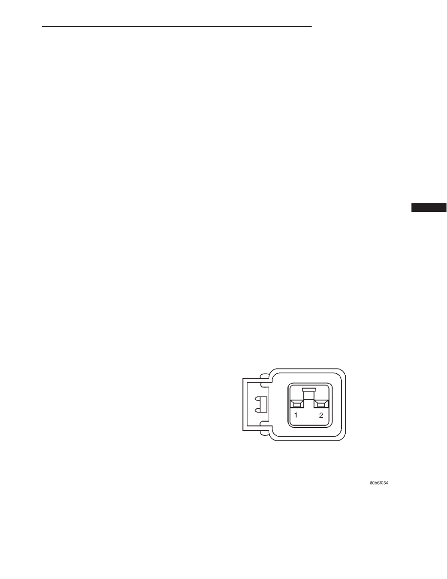
(1) Disconnect wire connector at horn.
(2) Using a voltmeter, connect one lead to ground
terminal and the other lead to the horn relay output
wire terminal (Fig. 1).
Fig. 1 Horn Connector Pin Call - Out
JX
HORN SYSTEMS
8G - 1

(3) Depress
the
horn
switch,
battery
voltage
should be present.
(4) If no voltage, refer to Horn Does Not Sound. If
voltage is OK, go to Step 5.
(5) Using ohmmeter, test ground wire for continu-
ity to ground.
(6) If no ground repair as necessary.
(7) If wires test OK and horn does not sound,
replace horn.
HORN CONTACT SWITCH
The horn contact consist of,
• A contact switch is mounted between the Driver
Airbag Module and steering wheel
• The horn wire is attached to Driver Airbag Mod-
ule mounting bracket.
• When the Driver Airbag Module is pressed the
contact ring touches the bracket mounting bolts and
makes contact to ground. The ground signal is car-
ried to the horn relay and horn sounds.
(1) Ground horn wire (Fig. 2).
(2) If horn does not sound, check for corrosion on
wire, bracket or airbag contact ring and ensure horn
wire is properly connected.
(3) If bracket needs to be replaced, the steering
wheel must be replaced. If contact ring is bad the
Driver Airbag Module must be replaced.
(4) Refer to Group 8W, Wiring Diagrams if wire
circuit needs to be repaired.
HORN RELAY
(1) Remove horn relay from the Junction Block
(Fig. 3).
(2) Using ohmmeter, test between the Junction
Block relay terminal 7 and ground for continuity.
(a) When the horn contact is not depressed, no
continuity.
(b) Continuity to ground when horn contact is
depressed.
(c) If continuity is not correct, repair horn con-
tact or wiring as necessary. Refer to Group 8W,
Wiring diagrams.
(3) Insert a jumper wire between terminals 8 and
10 of the horn relay in the Junction Block.
(a) If horns sound replace relay.
(b) If the horns do not sound, install horn relay
and refer to Horn Test.
(4) Using voltmeter, test battery voltage:
(a) Test Junction Block horn relay terminals 6
and 8 for voltage from fuse 8.
(b) If not OK, repair as necessary. Refer to
Group 8W, Wiring Diagrams.
HORNS WILL NOT SOUND
Check horn fuse 14 in the Power Distribution Cen-
ter and fuse 8 in the Junction Block. If fuse is blown
refer to FUSE BLOWN section. If fuse is OK, refer to
FUSE OK section.
HORN CONNECTOR PIN CALL-OUT
PIN #
CIRCUIT NAME
1
GROUND
2
HORN RELAY OUTPUT
Fig. 2 Horn Contact—Typical
1 – AIR BAG MODULE
2 – CONTACT AREA (4) LOCATIONS
3 – MOUNTING BOLTS
4 – AIR BAG MOUNTING BRACKET
Fig. 3 Horn Relay Location
1 – CIRCUIT BREAKERS
2 – HORN RELAY
3 – H/LP RELAY
8G - 2
HORN SYSTEMS
JX
DIAGNOSIS AND TESTING (Continued)
Нет комментариевНе стесняйтесь поделиться с нами вашим ценным мнением.
Текст